High efficiency drier with heating and drying zones

a high-efficiency, drying zone technology, applied in drying machines with progressive movements, lighting and heating apparatus, furnaces, etc., can solve the problem of unsaturated state of drying fluid, and achieve the effect of high energy efficiency, convenient use, and low cos

Inactive Publication Date: 2008-08-07
THE SHIVVERS GROUP
View PDF98 Cites 27 Cited by
  • Summary
  • Abstract
  • Description
  • Claims
  • Application Information

AI Technical Summary

Benefits of technology

[0022]Therefore, the objects of the invention are: to provide a drier that is highly efficient with respect to use of energy; to provide such a drier wherein heat is recovered and reused; to provide such a drier having a plurality of heating compartments and drying compartments alternatively located along the path of flow that the material to be dried traverses through the drier; to provide such a drier wherein heating fluid is flowed generally overall concurrently with respect to the material while drying fluid is flowed generally overall countercurrently with respect to the material through the drier; to provide such a drier wherein heating fluid and drying fluid is flowed concurrently, countercurrently, cross, mixed or otherwise through individual heating compartments and drying compartments; to provide such a drier where, when only one heating region is coupled with only one drying region, the heating fluid may flow countercurrent to the flow of the material; to provide such a drier wherein drying fluid exiting the drier is utilized to preheat heating fluid entering the drier; to provide such a drier where a heat pump may be utilized to further extract heat from the drying fluid that is exhausted from the drier and thereafter use the extracted heat to preheat the material, to add head to the drier elsewhere, or the like; to provide such a drier that is comparatively inexpensive to operate, easy to use and especially well adapted for the intended usage thereof and to provide a process for effectively utilizing such a drier.
[0023]Other objects and advantages of this invention will become apparent from the following description taken in conjunction with the accompanying drawings wherein are set forth, by way of illustration and example, certain embodiments of this invention.
[0024]The drawings constitute a part of this specification and include exemplary embodiments of the present invention and illustrate various objects and features thereof.

Problems solved by technology

It is further noted that the unsaturated state of the drying fluid may be the result of being heated by the material and that the drying fluid could be saturated or almost fully saturated when initially entering the drying chamber in some embodiments.

Method used


Image

  • High efficiency drier with heating and drying zones
  • High efficiency drier with heating and drying zones
  • High efficiency drier with heating and drying zones

Examples


Embodiment Construction

[0035]As required, detailed embodiments of the present invention are disclosed herein; however, it is to be understood that the disclosed embodiments are merely exemplary of the invention, which may be embodied in various forms. Therefore, specific structural and functional details disclosed herein are not to be interpreted as limiting, but merely as a basis for the claims and as a representative basis for teaching one skilled in the art to variously employ the present invention in virtually any appropriately detailed structure.

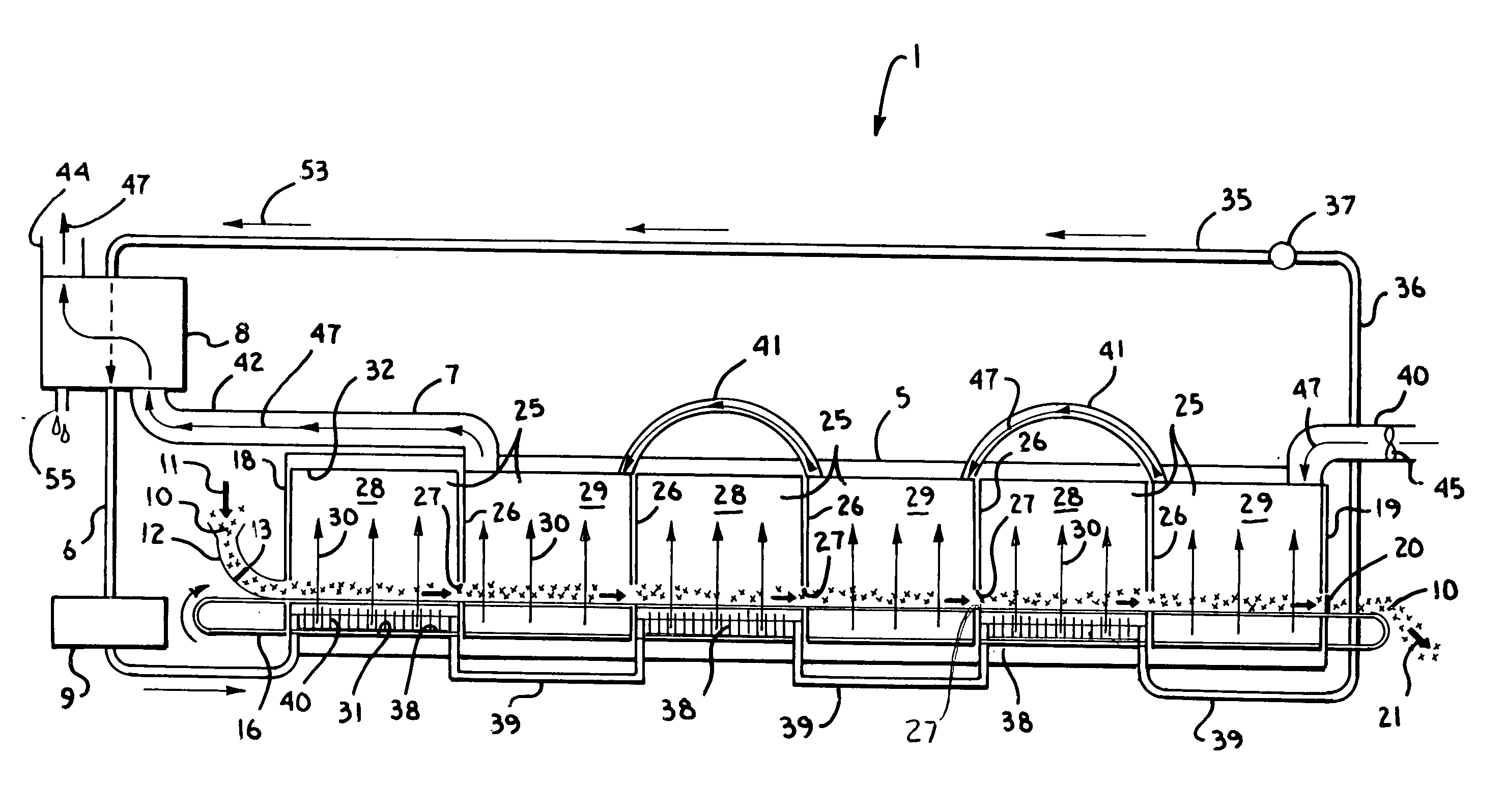
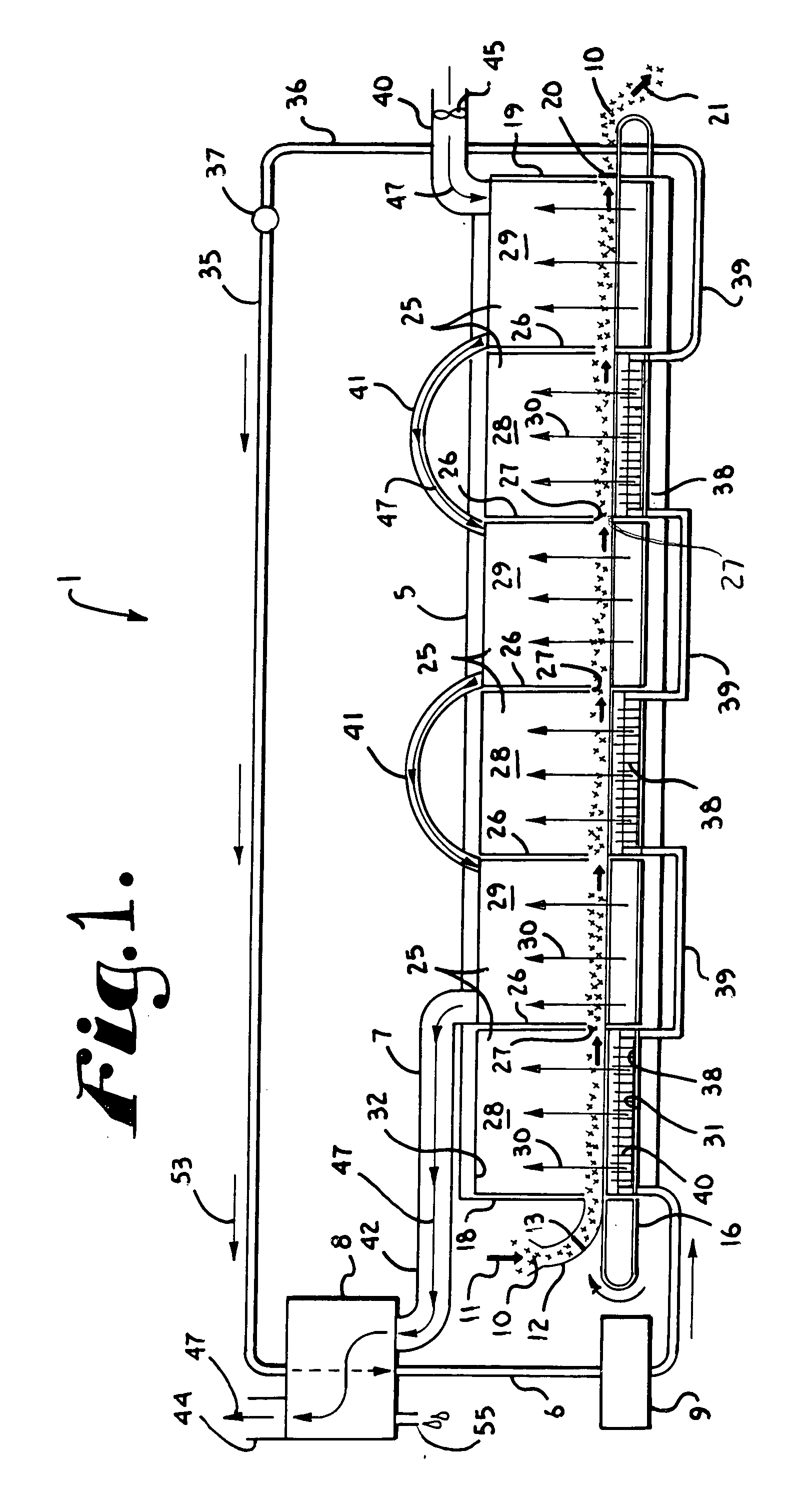
[0036]A particulate drier is shown in FIG. 1 generally indicated by the reference numeral 1. The drier 1 includes a drying chamber 5, a heating fluid recirculation system 6, a drying fluid recirculation system 7, a heating fluid regenerator 8 and a makeup heater 9. The drier 1 is for drying particulate material 10 generally represented by x's.

[0037]The particulate material 10 is fed as indicated by the reference numeral 11 into a feeder 12 having an air lock ...


PUM


Abstract

A drier for drying wet material includes a drying chamber with a plurality of heating region regions and a plurality of drying regions, alternatively located along the path of the material through the drier. Each of the heating regions is heated with heating fluid by a heating recirculation system wherein the heating fluid overall flows in heat exchange with the material in the chamber, but wherein the heating fluid can flow in various ways within each heating region. A fluid circulation system flows drying fluid through each of the drying regions generally in countercurrent flow relative to the flow of material through the drier, although the drying fluid can flow in various ways within each drying region. The drying fluid exiting the drier is used to preheat the heating fluid exiting the drier prior to the heating fluid reentering the drier. Makeup heat is supplied to the system.

Description

CROSS REFERENCE TO RELATED APPLICATIONS[0001]This application is a continuation-in-part of U.S. patent application Ser. No. 12 / 012,551, filed Feb. 4, 2008 that claims the benefit of U.S. Provisional Application No. 60 / 899,227, filed Feb. 2, 2007 the disclosures of which are incorporated by reference herein.STATEMENT REGARDING UNITED STATES GOVERNMENT SPONSORED RESEARCH OR DEVELOPMENT[0002]The present invention was at least in part made with support from the United States Government under Contract No. 2005-33610-15517 awarded by the USDA SBIR. The United States Government has certain rights in the invention.BACKGROUND OF THE INVENTION[0003]The present invention is directed to improvements in driers and methods of drying used to dry various materials, including newly harvested grain, wood pellets, and particulate materials of all types and, in particular, to driers that utilize fluid to heat the material, cool and dry the material with generally overall countercurrent air flow and rec...

Claims


Application Information

Patent Timeline
Patent Type & Authority Applications(United States)
IPC IPC(8): F26B3/06F26B25/06
CPCF26B3/08F26B15/12F26B15/143F26B23/10F26B17/04F26B17/16F26B17/20F26B17/005
Inventor SHIVVERS, STEVE D.
Owner THE SHIVVERS GROUP
Why Eureka
Try Eureka