Turbochanger system for internal combustion engine comprising two compressor stages of the radial type provided with compressor wheels having backswept blades

a technology of internal combustion engine and compressor wheel, which is applied in the direction of liquid fuel engine, machine/engine, electric control, etc., can solve the problems of poor utilization of fuel energy resources and poor efficiency, and achieve the effect of improving efficiency and better use of engine energy in the exhaust flow

Inactive Publication Date: 2006-06-15
VOLVO LASTVAGNAR AB
View PDF18 Cites 14 Cited by
  • Summary
  • Abstract
  • Description
  • Claims
  • Application Information

AI Technical Summary

Benefits of technology

[0005] One object of the present invention is therefore to produce an economically feasible turbocharger system which makes better use of the energy in the exhaust flow of the engine, for increased efficiency, and without engendering significant spatial requirements.

Problems solved by technology

Until now, environmental demands upon diesel engines have usually led to worsened efficiency, which has therefore meant that the energy resource of the fuel has not been well utilized.

Method used


Image

  • Turbochanger system for internal combustion engine comprising two compressor stages of the radial type provided with compressor wheels having backswept blades
  • Turbochanger system for internal combustion engine comprising two compressor stages of the radial type provided with compressor wheels having backswept blades
  • Turbochanger system for internal combustion engine comprising two compressor stages of the radial type provided with compressor wheels having backswept blades

Examples


Embodiment Construction

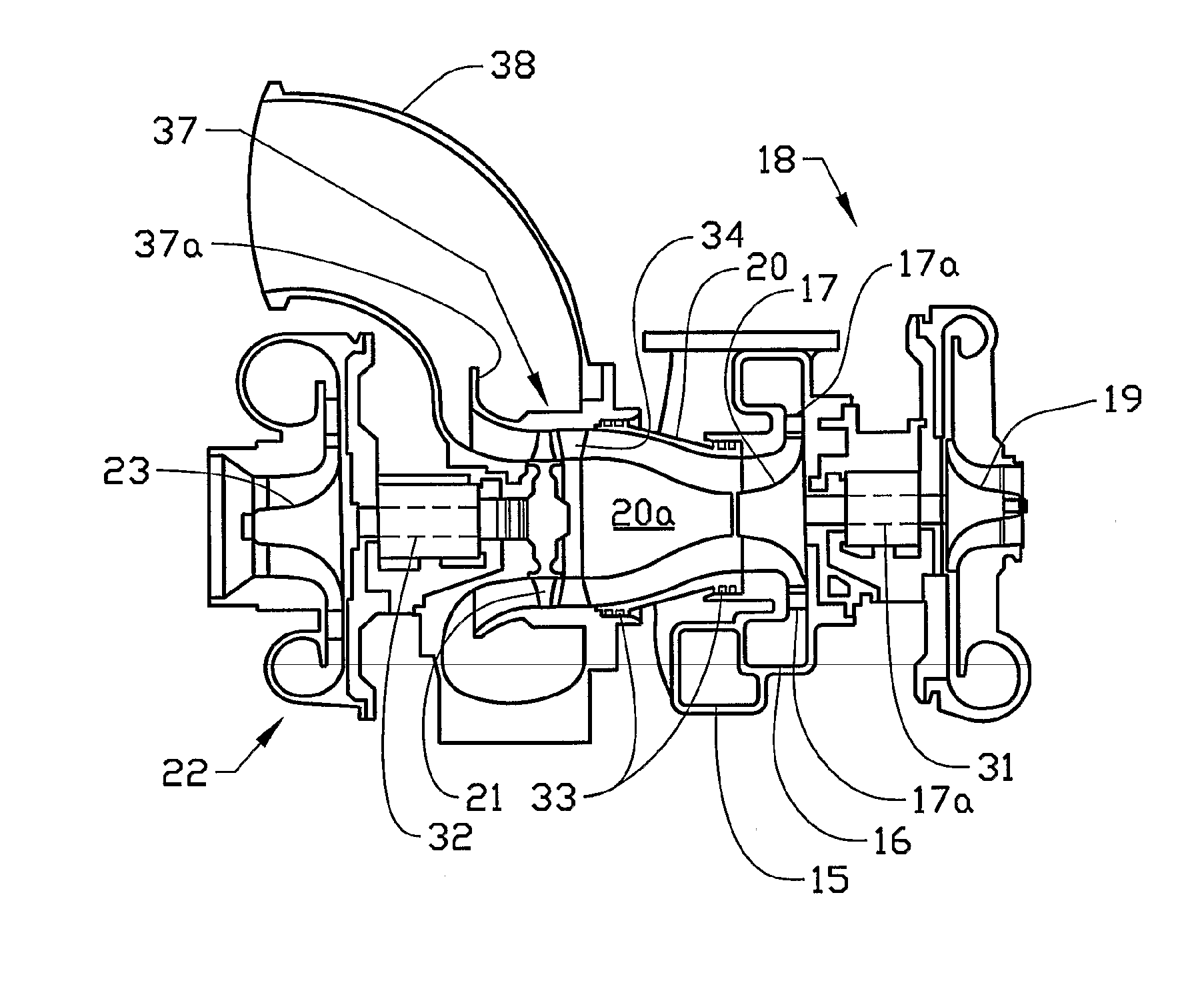
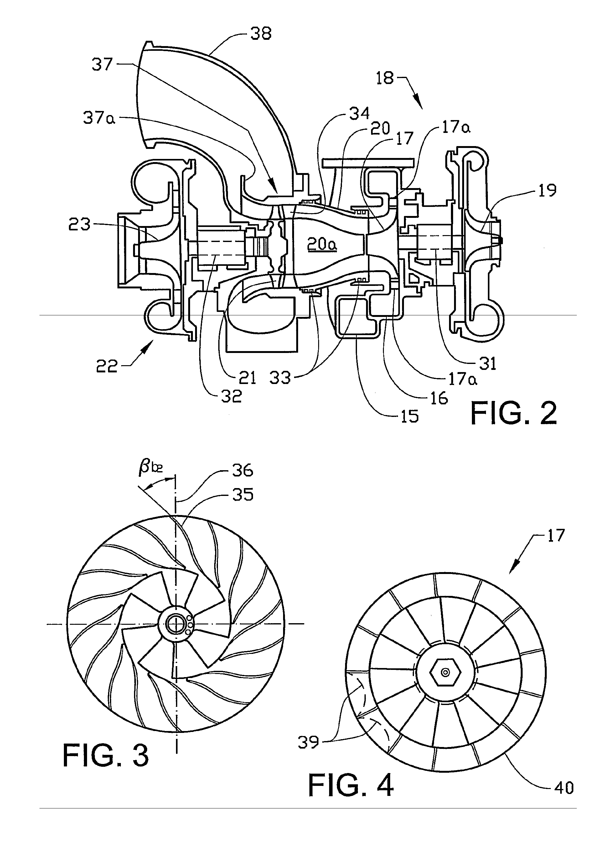
[0012] The invention relates to a supercharging system for, in the first place, diesel engines having a cubic capacity of between about 6 liters and about 20 liters, for use preferably in heavy-duty vehicles such as trucks, buses and construction machinery. The supercharging system has the characteristic that it offers a considerably more effective supercharge than current systems. The supercharge. is realized in two stages with two series-connected, radial-type compressors with intermediate cooling. The first compressor stage, referred to as the low-pressure compressor, is driven by a low-pressure turbine of the axial type. The second compressor stage, the high-pressure compressor, is driven by a high-pressure turbine of the radial type.

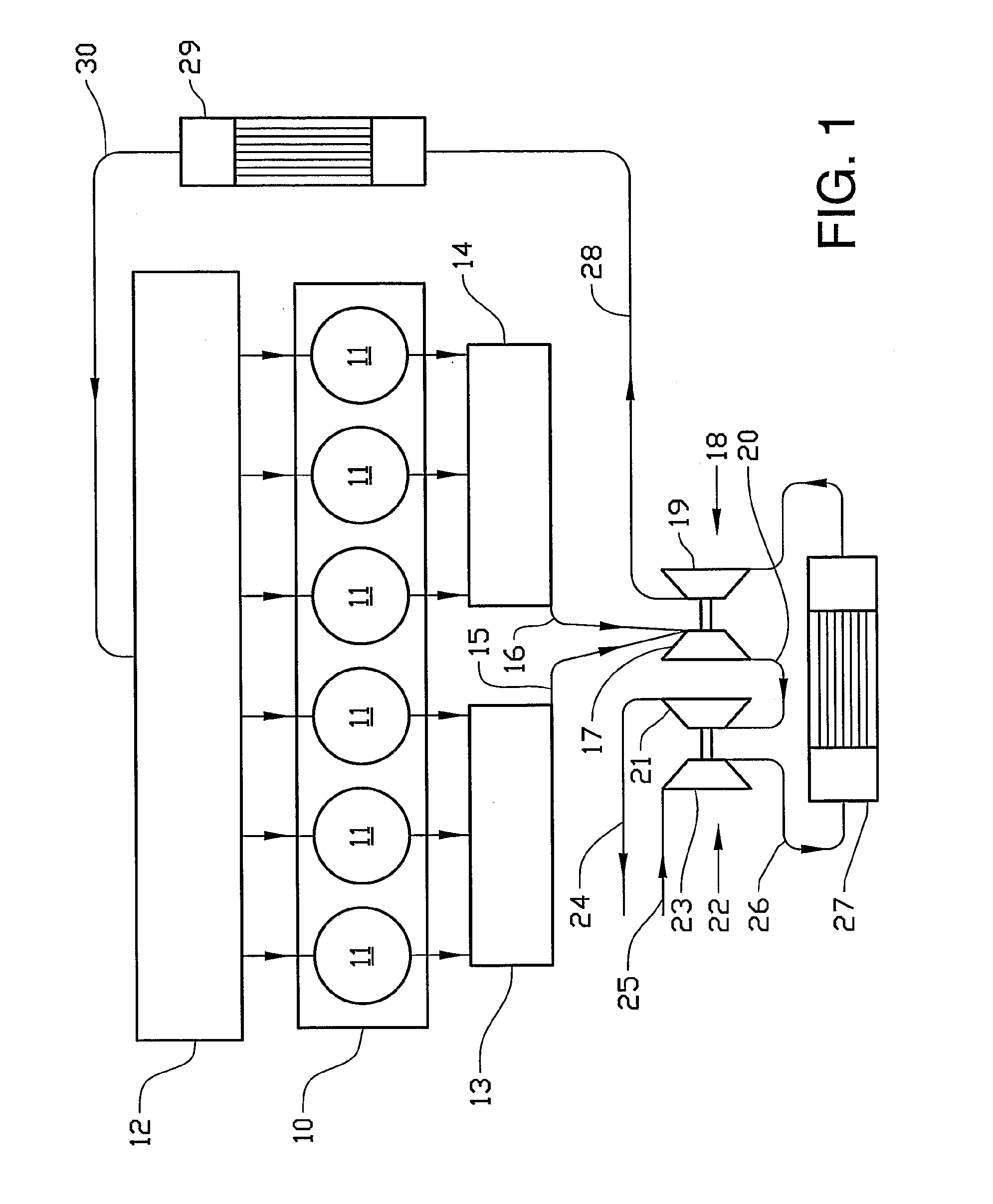
[0013]FIG. 1 shows an engine block 10 having six engine cylinders 11, which communicate in a conventional manner with an inlet manifold 12 and two separate exhaust manifolds 13, 14. Each of these two exhaust manifolds receives exhaust gases from th...


PUM


Abstract

A turbocharger system for an internal combustion engine having at least one exhaust line (15, 16) for evacuating exhaust gases from the combustion chamber of the engine and at least on inlet line for supplying air to the combustion chamber. A high-pressure turbine (17) interacts with a high-pressure compressor (19) and a low-pressure turbine (21) interacts with a low-pressure compressor (23) in order to extract energy from the exhaust flow of the engine and pressurize the inlet air of the engine. Both compressor stages are of the radial type and are provided with compressor wheels having backswept blades, in which a blade angle between an imaginary extension of the blade along the centerline between root section and tip section in the direction of the outlet tangent and a line connecting the center axis of the compressor wheel to the outer point of the blade, is at least about 40 degrees. The high-pressure turbine (17) is of the radial type and is connected to the low-pressure turbine by a short intermediate duct (20). The low-pressure turbine (21 ) is provided with inlet guide rails (34).

Description

FIELD OF THE INVENTION [0001] The present invention relates to a turbocharger system for an internal combustion engine having at least one exhaust line for evacuating exhaust gases from the combustion chamber of the engine and at least one inlet line for supplying air to the combustion chamber. A high-pressure turbine, interacting with a high-pressure compressor, and a low-pressure turbine, interacting with a low-pressure compressor, are also included for extracting energy from the exhaust flow of the engine and pressurizing the inlet air of the engine. BACKGROUND OF THE INVENTION [0002] Turbocharger systems for supercharging diesel-type internal combustion engines, preferably for heavy-duty vehicles, usually include a single-stage compressor driven by a single-stage turbine, both of the radial type. Turbocharger systems with two-stage supercharge sometimes also include intermediate cooling, but the construction is usually based on standard assemblies intended for single-stage super...

Claims


Application Information

Patent Timeline
Patent Type & Authority Applications(United States)
IPC IPC(8): F02B33/44F01D5/04F01N13/14F02B3/06F02B23/06F02B29/04F02B37/00F02B37/013F02B37/02F02B41/10F02D41/00F02D41/40F02M25/07F04D29/28
CPCF01D5/048F01N13/107F02B3/06F02B23/0672F02B29/0412F02B29/0418F02B29/0425F02B29/0493F02B37/00F02B37/013F02B37/02F02B37/025F02B41/10F02B2275/14F02D41/40F02D2041/001F02M25/0707F02M25/0711F02M25/0727F02M25/0738F04D29/284Y02T10/125Y02T10/146Y02T10/44Y02T10/123Y02T10/144Y02T10/163F02B37/004F05D2220/40F02M26/05F02M26/08F02M26/23F02M26/33Y02T10/12Y02T10/40
Inventor GOBERT, ULRICHSUNDIN, LARSISING, MAGNUSGRUNDITZ, DANIELANDERSSON, PERGISELMO, KENTKRAUSCHE, SEBASTIAN
Owner VOLVO LASTVAGNAR AB
Why Eureka
Try Eureka