Diffraction grating, light source unit applying the same therein, and optical head device employing the same

a technology of light source unit and optical head, applied in the field of optical head, can solve the problems of diffraction efficiency, offset in push-pull signal, and one problem, and achieve the effect of increasing the optical energy utilizabl

Inactive Publication Date: 2007-01-16
RICOH KK
View PDF23 Cites 14 Cited by
  • Summary
  • Abstract
  • Description
  • Claims
  • Application Information

AI Technical Summary

Benefits of technology

[0026]An object of the present invention is to provide a polarization diffraction grating with a configuration in that an offset in a tracking servo signal occurring due to the diffraction characteristic of the grating's volume property can be effectively reduced even when the grating pitch is reduced so as to miniaturize the machine which employs the device.
[0028]Furthermore, another object of the present invention is to provide a polarization diffraction grating in that a +1-th light diffraction efficiency occurring near the right-angle incidence even in case the grating pitch is made smaller can be improved, and to provide an optical head device which employs such an improved beam-slitting device, and thus, has a capability of reproducing information at a high reproduction rate.
[0032]Another object of the present invention is to provide a semiconductor laser unit acting as a light source of an optical head device or so, which employs a polarization hologram device as a beam splitting device, and has an improved light-receiving efficiency in a light-receiving device for a beam incident thereonto through the polarization hologram device.
[0042]As illustrated in FIG. 8 or FIG. 19, a diffraction grating has a feature of light-incidence-angel-dependent diffraction efficiency such that the diffraction efficiency thereof on +1-th diffraction has a peak for a light incident angle not coincident with the right angle but shifted therefrom by a predetermined angle (Bragg angle). According to the present invention, the diffraction grating itself is inclined with respect to a plane perpendicular to the optical axis of the light source or a direction of a chief ray of a beam incident onto the diffraction grating by a predetermined angle, or each boundary line between different types of media which form the diffraction grating is inclined by a predetermined angle (as shown in FIGS. 4 through 7). Thereby, it becomes possible to effectively increase the optical energy utilizable in the diffracted light received through the diffraction grating, with respect to the optical energy of a light incident on the diffraction grating, and, thus, to effectively improve the optical energy usage efficiency in the optical head device or semiconductor laser unit, effectively.

Problems solved by technology

However, when the pitch is made smaller, one problem may occur.
This is a problem concerning an angle-dependency of the diffraction efficiency. FIG. 2 shows a relation between the incidence angle onto the polarization diffraction grating and the +1-th diffraction efficiency.
When the pitch of the diffraction grating is made smaller and thus the polarization diffraction grating having the characteristic of the above-mentioned volume-type grating is used in an optical head device so as to dispose the polarization diffraction grating nearer to a light source part and thus miniaturize an optical system needed around the light source and an light detection device, a problem may arise.
Such an imbalance in the diffraction efficiency between both sides causes an offset in the push-pull signal.
Thereby, even when the optical head is positioned accurately on a track, the tracking servo signal does not indicate a zero value, and, thus, a proper tracking servo control may not be achieved in the optical disk drive.
However, when the grating pitch is made smaller as mentioned above, the diffraction efficiency has a peak at a specific incidence angle (Bragg angle) other than the right angle, and thus, the diffraction efficiency near the right-angle incidence may be degraded relatively.
Accordingly, the actually applicable substantial overall diffraction efficiency may not be high enough.
Moreover, a variation in the diffraction efficiency may also occur not only due to a particular product but also due to some error in assembly of a polarization hologram device into an optical pickup, or so.
By these factors, the actually applicable diffraction efficiency thereof may not be expected sufficiently high.

Method used


Image

  • Diffraction grating, light source unit applying the same therein, and optical head device employing the same
  • Diffraction grating, light source unit applying the same therein, and optical head device employing the same
  • Diffraction grating, light source unit applying the same therein, and optical head device employing the same

Examples


third embodiment

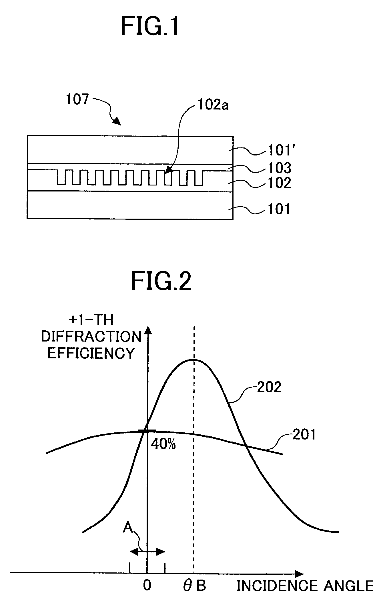
[0075]the present invention will now be described. When applying the above-mentioned polarization diffraction grating as a beam-splitting device in an optical head device, in order to prevent creation of an offset in the push-pull signal which is used as a tracking signal, it is preferable that the peak of diffraction efficiency should occur at an angle of 0 degrees, i.e., at a time of the right-angle or perpendicular beam incidence.

[0076]In order to cause the peak of diffraction efficiency to occur at a time of perpendicular beam incidence as the Bragg angle, assuming that the diffraction angle α in the diffraction grating medium at the time of perpendicular beam incidence is expressed as α=α0, as shown in FIG. 5B and FIG. 7, a setting should be made such that θB′=0 in the above-mentioned formula (3),

α0−2β=0,

and thus, when,

β=α0 / 2  (4)

the +1-th diffraction efficiency has a peak at the occasion of the perpendicular beam incidence.

[0077]The curve 43 of FIG. 8 denotes the +1-th diffrac...

fourth embodiment

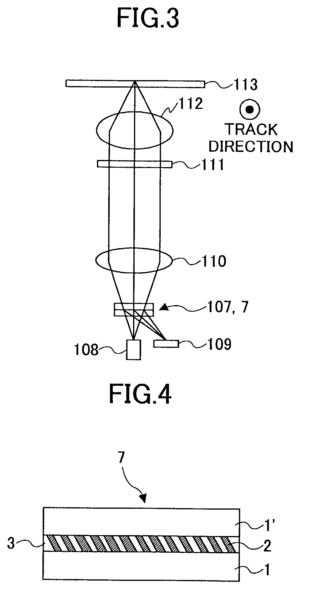
[0081]the present invention will now be described. As shown in FIG. 3, when the polarization diffraction grating 7 is disposed in a convergent beam reflected by an optical recording medium, since the incident beam includes various incidence angles as shown in FIG. 5B, i.e., incident beam elements 0, 1 and 2, for example, it becomes not possible to obtain a peak diffraction efficiency for each of all elements of the incident beam merely by applying a representative single incident angle to the formula (4). In order to obtain the peak diffraction efficiency for each of all elements of the incident beam, the inclination angles of respective rectangular elements of the patterned-indented shape of the polarization diffraction grating should be set differently depending on the actual incident angles of respective beam elements.

[0082]That is, in FIG. 5B, for an area for the incident beam element 0, as has been described in the description of the third embodiment above, in the diffraction g...

ninth embodiment

[0117]FIG. 13 shows an outline configuration of a two-wavelength optical head device according to the present invention employing the polarization diffraction grating 7 according to any of the embodiments mentioned above according to the present invention. As shown, this optical head device includes a light source 8 made of a semiconductor laser or so for the wavelength of 780 nm, and another light source 8′ made of a semiconductor laser or so for the wavelength of 660 nm. Other than them, the optical head device includes the polarization diffraction grating 7 according to the embodiment of the present invention, a collimator lens 10, a ¼-wavelength plate 11, an object lens 12 which has undergone aberration correction for the two wavelengths of 780 nm and 660 nm, and a light detection device 9 made of a multi-beam-incidence-area-divided photodiode or so, and performs recording / reproduction of information on / from an optical recording medium (optical disk) 13.

[0118]Since this two-wave...


PUM

PropertyMeasurementUnit
incidence angleaaaaaaaaaa
Bragg angleaaaaaaaaaa
wavelengthaaaaaaaaaa

Abstract

A polarization diffraction grating includes two media having different orientation states arranged alternately and cyclically, wherein each boundary between the media forms an oblique rectangular shape.

Description

BACKGROUND OF THE INVENTION[0001]1. Field of the Invention[0002]The present invention relates to an optical head device in an optical disk drive which can carry out recording / reproduction of information into / from an optical recording media (optical disks) in a plurality of standards having different operation wavelengths, i.e., at least some of CDs (compact disks), DVDs (digital versatile disks), S-DVDs, disks applicable for a blue operation wavelength and so forth, with an employment of a polarization diffraction grating or a polarization hologram device for a beam splitting purpose therein.[0003]2. Description of the Related Art[0004]An optical system which splits a beam with a diffraction device and applies a reflected light from an optical disk which is an optical information recording medium onto a light detection device is provided in an optical head device (optical pickup) of an optical disk drive in various types. As the above-mentioned diffraction device, a polarization dif...

Claims


Application Information

Patent Timeline
Patent Type & Authority Patents(United States)
IPC IPC(8): G02B5/18G11B7/00G11B7/12G11B7/125G11B7/135
CPCG11B7/1205G11B7/1275G11B7/1365G11B7/1353G11B2007/0006G11B7/123
Inventor FUNATO, HIROYOSHIKITABAYASHI, JUNICHIOOHCHIDA, SHIGERUSUZUDO, TSUYOSHI
Owner RICOH KK
Why Eureka
Try Eureka