High-throughput continuous-flow ultrasound reactor

a continuous-flow, high-throughput technology, applied in the direction of mechanical vibration separation, oxygen/ozone/oxide/hydroxide, surgery, etc., can solve the problem of high sensitive value of processing cost, and achieve the effect of high-efficiency energy us

Inactive Publication Date: 2005-12-15
SULPHCO
View PDF8 Cites 14 Cited by
  • Summary
  • Abstract
  • Description
  • Claims
  • Application Information

AI Technical Summary

Benefits of technology

[0007] It has now been discovered that ultrasound treatment can be applied to a fluid material on a continuous-flow basis with a highly efficient use of energy by incorporating certain structural improvements in the reaction vessel and the ultrasound components.

Problems solved by technology

Ultrasound processing offers a vast potential for the petroleum industry, but its value is highly sensitive to processing costs, and particularly the energy consumption involved in generating the ultrasonic vibrations.

Method used


Image

  • High-throughput continuous-flow ultrasound reactor
  • High-throughput continuous-flow ultrasound reactor

Examples


Embodiment Construction

[0012] While this invention is susceptible to a variety of implementations and configurations, a detailed study of a specific system within the scope of the invention will provide the reader with a full understanding of the concepts of the invention as a whole and how they can be applied. One such system is shown in the Figure.

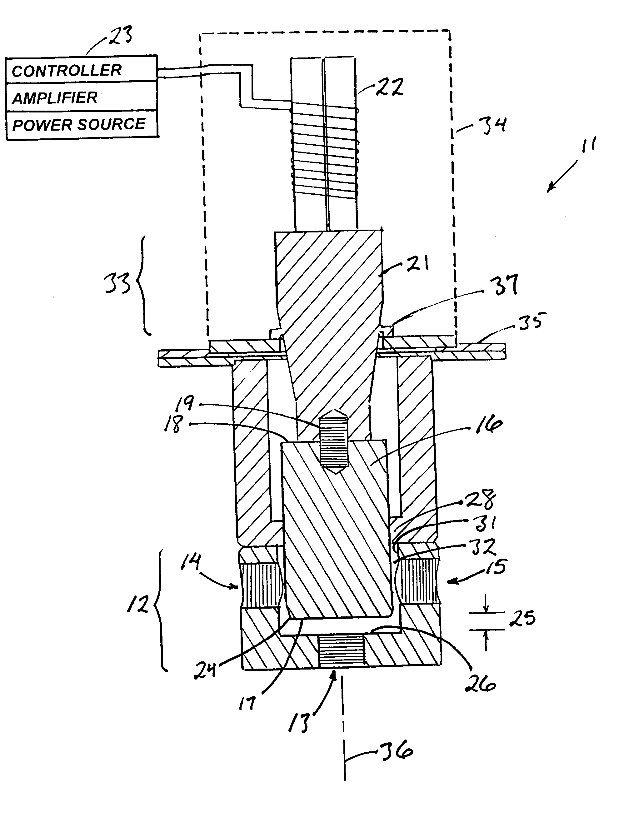
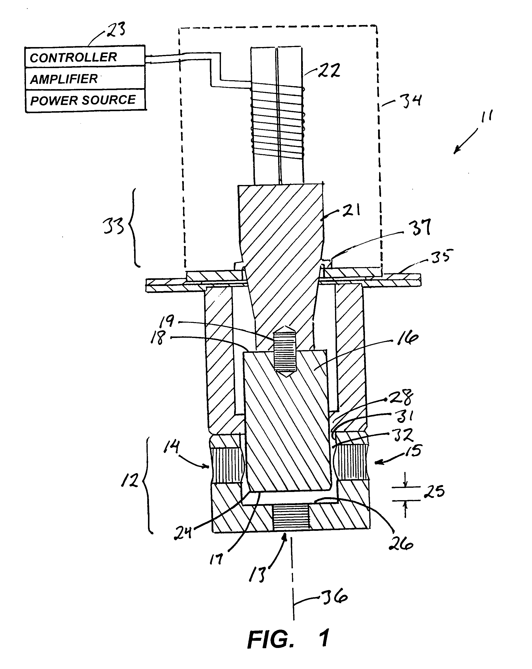
[0013]FIG. 1 is an axial cross section of a continuous-flow reactor 11 in which a flowing reaction medium is exposed to ultrasound in accordance with this invention. The reactor consists of a reaction chamber 12 with an entry port 13 for the inflow of the reaction medium and exit ports, of which two 14, 15 are shown, through which the treated reaction medium leaves the chamber. Mounted to the reactor is an ultrasonic horn 16 whose distal end 17 extends into the interior of the reaction chamber 12. The proximal end 18 of the horn is joined by way of a coupling stud 19 to a connecting block 21 that in turn is joined to an ultrasonic transducer 22. The connectin...


PUM

PropertyMeasurementUnit
flow rateaaaaaaaaaa
flow rateaaaaaaaaaa
frequencyaaaaaaaaaa

Abstract

Liquids are treated by ultrasound in a flow-through reaction vessel with an elongate ultrasonic horn mounted to the vessel with one end of the horn extending into the vessel interior. The liquid flow path inside the vessel is such that the entering liquid strikes the end of the horn at a direction normal to the end, then flows across the surface of the end before leaving the vessel. The end surface of the horn is positioned in close proximity to the entry port to provide a relatively high surface-to-volume ratio in the immediate vicinity of the horn end. In a further improvement, the horn is joined to an ultrasonic transducer through a booster block that provides an acoustic gain to the ultrasonic vibrations, and the booster block is plated with a reflective metal to lessen any loss of ultrasonic energy being transmitted to the horn.

Description

BACKGROUND OF THE INVENTION [0001] 1. Field of the Invention [0002] This invention resides in the field of process equipment used in the treatment of materials in liquid media by ultrasound, and also in the processing of petroleum and petroleum-based fuels. [0003] 2. Description of the Prior Art [0004] The use of ultrasound for driving chemical reactions is well known. Descriptions are found in Suslick, K. S., Science 247: 1439 (1990), and Mason, T. J., Practical Sonochemistry, A User's Guide to Applications in Chemistry and Chemical Engineering, Ellis Norwood Publishers, West Sussex, England (1991). A variety of ultrasound systems have been described, and among the most prominent are “probe”-type systems, which include an ultrasonic transducer that generates ultrasonic energy and transmits that energy to a probe, i.e., an ultrasonic horn, for amplification. [0005] Uses of ultrasound have recently been extended to include petroleum processing, notably for the desulfurization of foss...

Claims


Application Information

Patent Timeline
Patent Type & Authority Applications(United States)
IPC IPC(8): B06B3/00A61B17/20B32B5/02C01B13/00B01J19/10
CPCB01J19/10B01J2219/0869B01J2219/0871B01J2219/0877B01J2219/0888B01J2219/0892B06B3/00C10G32/02
Inventor GUNNERMAN, RUDOLF W.
Owner SULPHCO
Why Eureka
Try Eureka