Energy accumulator module

a technology of energy accumulator and energy storage unit, which is applied in the manufacture of cell components, final product details, cell components, etc., can solve the problems of increasing assembly difficulty of corresponding energy storage units and additional connection components, and achieves simple insertion, reduce assembly costs, and accelerate assembly

Inactive Publication Date: 2011-08-04
MAGNA E CAR SYSEMS & OG
View PDF15 Cites 13 Cited by
  • Summary
  • Abstract
  • Description
  • Claims
  • Application Information

AI Technical Summary

Benefits of technology

[0016]In case at least some of the interconnection means are plug-in connectors, which are in particular detachable, assembly or connection of two energy storage modules can be realized by simple insertion, which accelerates assembly and reduces assembly costs. By providing a detachable connection, a defective module forming a constituent part of a larger energy storage unit can, for example, be replaced in a simple manner.
[0017]Provision can be made for the energy storage module having a connect

Problems solved by technology

The problem therewith is often that the interconnection of the individual modules, i.e. their appropriate connection to one another, is realized in a relatively

Method used


Image

  • Energy accumulator module
  • Energy accumulator module
  • Energy accumulator module

Examples


Embodiment Construction

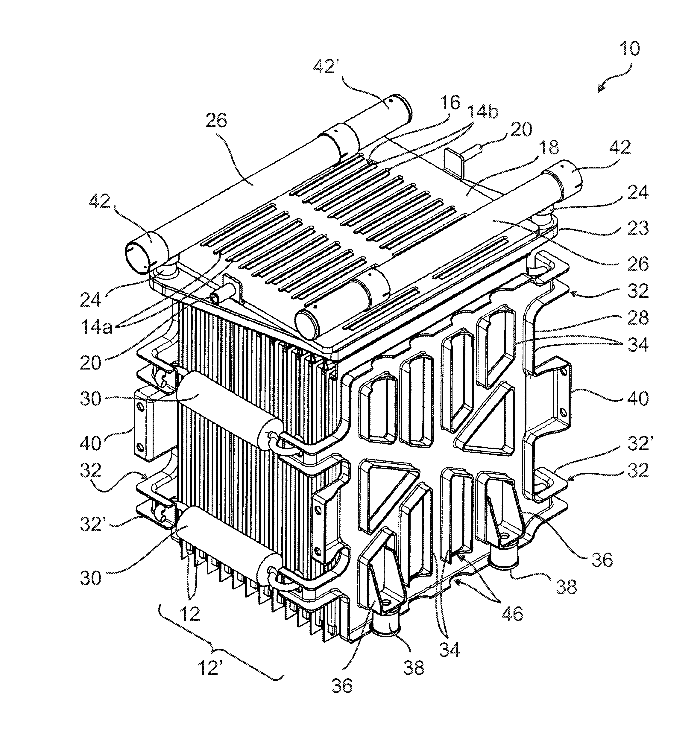
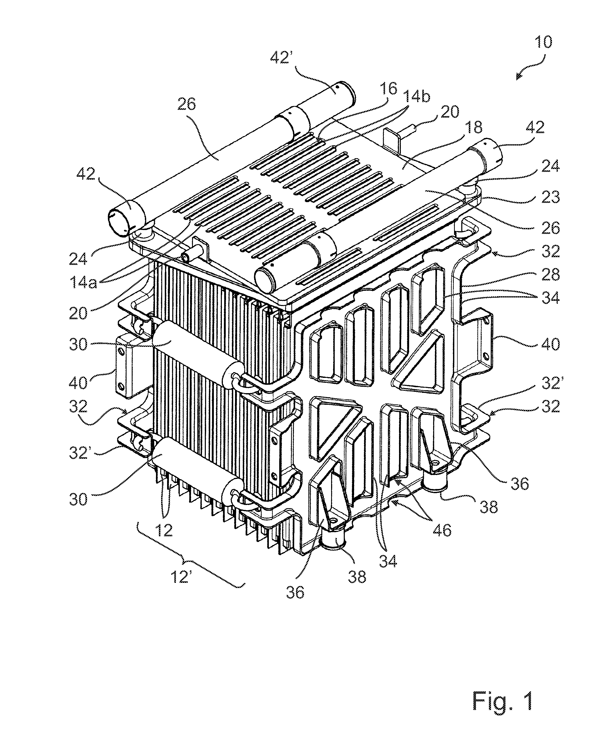
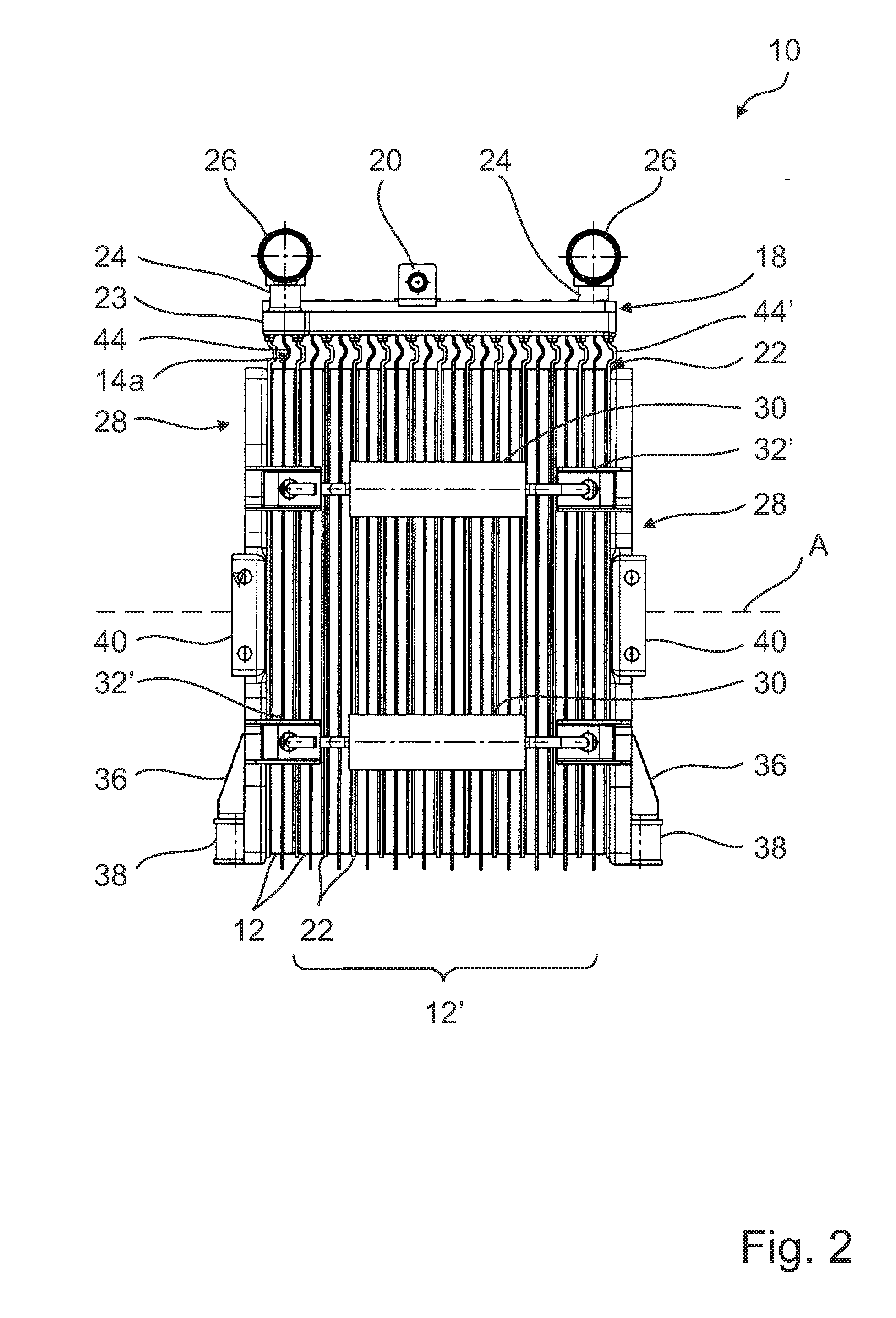
[0044]FIG. 1 shows a perspective view of an energy storage module 10 comprising a plurality of prismatic cells / flat cells 12 arranged in a cell stack 12′ in parallel with respect to one another. The flat cells 12 can, for example, be lithium-ion accumulator cells or double-layer capacitor cells (“supercaps”). Each of the individual cells 12 has two electrode tabs 14a, 14b, which are inserted through slots 16 of an interconnection board 18 provided for this purpose. The electrode tabs 14a, 14b reach through the interconnection board 18 and are, at the free top side thereof—i.e. at the side of the interconnection board 18 facing away from the flat cells 12-, connected to contact surfaces not shown, in order to provide electrical contact between the flat cells 12. The contacting between the flat cells 12 can, for example, be parallel or serial or comprise a mixed form of parallel and serial contacting.

[0045]The electrical energy stored in the flat cells 12 can be tapped via a plug and ...


PUM


Abstract

An energy storage module having a plurality of stacked flat cells. The energy storage module has an interconnection formed in such a way that the energy storage module can be connected mechanically, electrically and/or for exchanging coolant with at least one other energy storage module of the same kind.

Description

BACKGROUND OF THE INVENTION[0001]The present invention relates to an energy storage module having a plurality of stacked flat cells.[0002]Energy storage modules of this kind are used in a plurality of devices, especially in motor vehicles. They can be combined in order to create an energy storage unit consisting of several modules and having the performance features required in each individual case.[0003]The problem therewith is often that the interconnection of the individual modules, i.e. their appropriate connection to one another, is realized in a relatively extensive manner and that normally additional connection components are required. This also makes assembly of the corresponding energy storage unit more difficult.[0004]It is therefore an object of the present invention to provide an energy storage module which is compact and can be mounted in a simple manner. Furthermore, the energy storage module is to be reliable and efficient.SUMMARY OF THE INVENTION[0005]This object is ...

Claims


Application Information

Patent Timeline
IPC IPC(8): H01M2/10H01M10/50H01M50/209H01M50/271H01M50/278H01M50/293H01M50/502H01M50/509H01M50/51H01M50/512
CPCH01M2/1077H01M2/1083H01M10/5004H01M10/5077H01M10/5053H01M10/5055H01M10/5016H01M10/625H01M10/6568H01M10/6555H01M10/6554H01M10/613H01M10/6556H01M10/0481Y02E60/10H01M50/502Y02P70/50H01M50/293H01M50/278H01M50/209H01M50/509H01M50/512H01M50/51H01M50/271H01M10/0468
Inventor MICHELITSCH, MARTINWUENSCHE, RALPHGEIDL, UWENIEDERL, DIETMAR
Owner MAGNA E CAR SYSEMS & OG
Why Eureka
Try Eureka