Heat pump for high purity bottom product

a technology of bottom product and heat pump, which is applied in the field of separation of hydrocarbons, can solve the problems of large energy consumption and inefficiency in energy consumption, and achieve the effects of increasing the purity of the bottom product, reducing the amount of external energy added, and improving energy efficiency

Active Publication Date: 2012-05-22
UOP LLC
View PDF21 Cites 15 Cited by
  • Summary
  • Abstract
  • Description
  • Claims
  • Application Information

AI Technical Summary

Benefits of technology

[0004]The present invention provides for a more efficient energy usage in the distillation of a mixture. The distillation improvement provides for increasing the purity of the bottoms product while reducing the amount of external energy added, or utility usage, to reboil the bottoms stream to create the vapor for stripping the lighter components from the bottoms stream.
[0005]The present invention utilizes the heat from an overhead vapor stream and intermediate vapor stream to reboil liquid from the bottoms stream and an intermediate liquid stream. The process comprises operating a distillation column where a portion of the bottoms liquid stream is drawn off and passed through a pressure reducing valve. This reduced pressure liquid is heat exchanged with a portion of the overhead vapor stream, thereby creating a vaporized bottoms stream and a condensed overhead stream. The overhead stream is passed to the top of the rectifying section as reflux. The vaporized bottoms stream is compressed through a heat pump compressor, thereby adding heat and bringing the stream to at least the column pressure, and then passed to the bottom of the stripping section. The process further comprises drawing off an intermediate liquid stream for reboiling and passing back to the column, preferably in the stripping section of the column. The intermediate liquid stream is passed through a pressure reducing valve and is heat exchanged with a second portion of the overhead vapor stream, where the liquid is vaporized and the overhead vapor is condensed. The condensed overhead stream is passed back to the top of the rectifying section as additional reflux. The vaporized intermediate stream is compressed by a heat pump compressor and passed back to the column at a pressure at least as great as the column pressure. The intermediate stream is preferably passed to a position above where the intermediate liquid stream was drawn off. This provides a method to purify the bottoms stream without having to add a significant amount of additional energy to the distillation column.

Problems solved by technology

A problem exists for distillation systems in that they are large consumers of energy and inefficient with respect to energy usage and consumption.

Method used


Image

  • Heat pump for high purity bottom product
  • Heat pump for high purity bottom product
  • Heat pump for high purity bottom product

Examples


Embodiment Construction

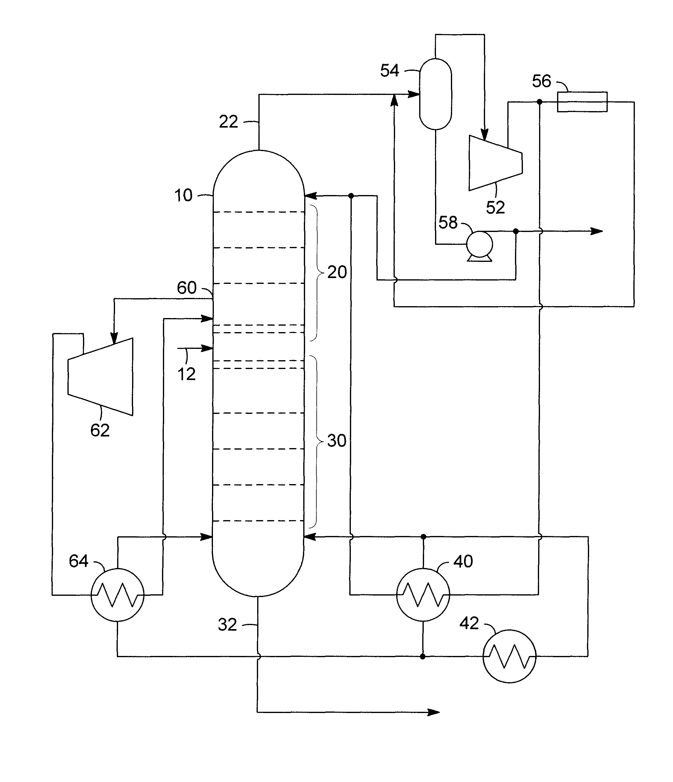
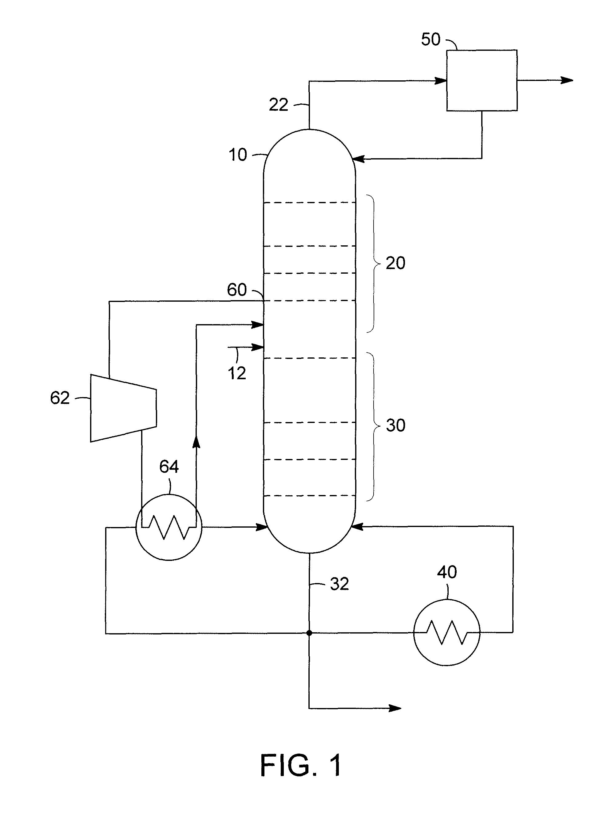
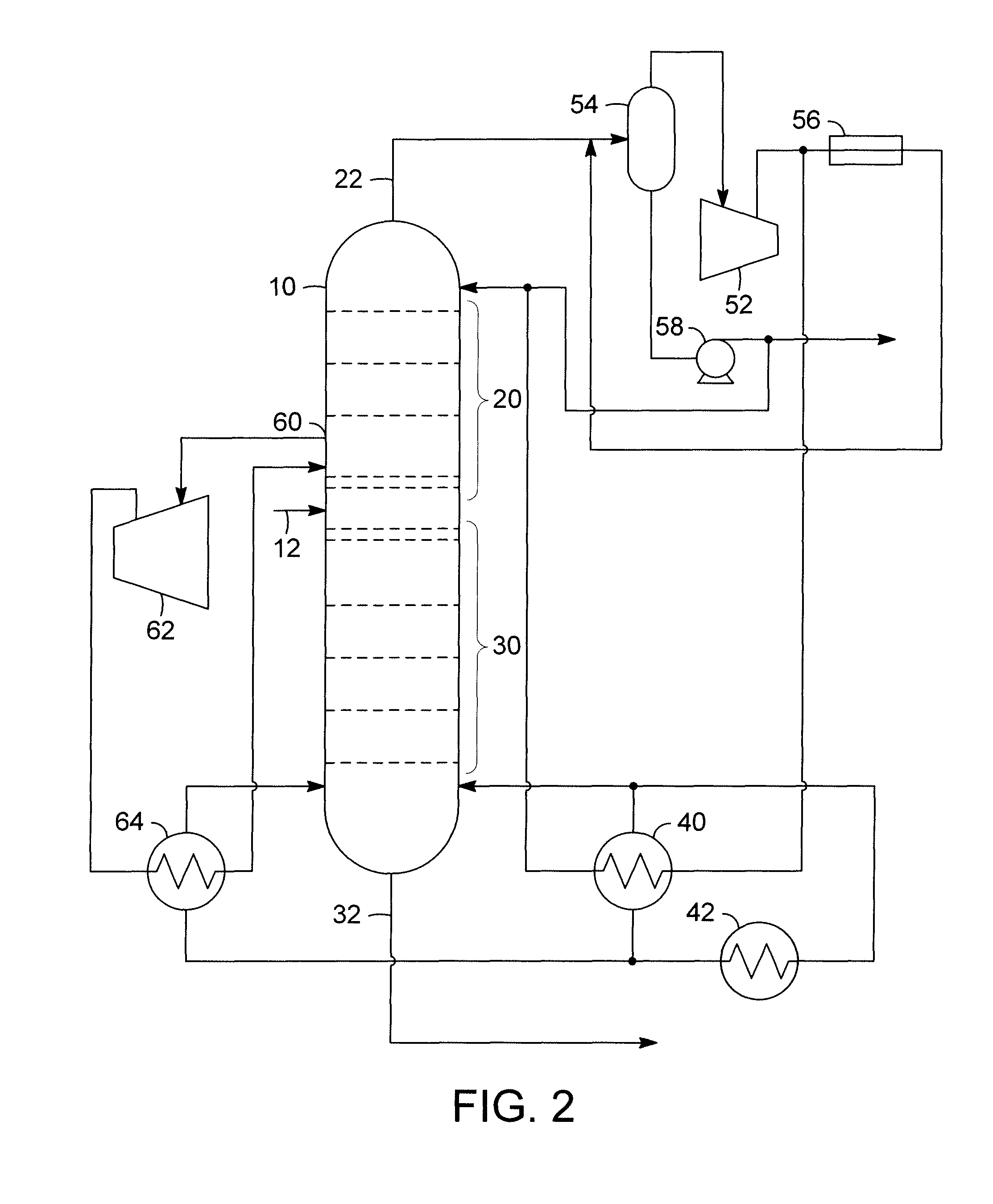
[0011]The separation of fluids is well known in art, and separation by distillation is a common means for separating two or more liquids. A distillation process operates on the principle of different liquid components in a mixture have different volatilities, and therefore will develop an equilibrium where for the more volatile component, the vapor phase has a higher concentration relative to that components concentration in the liquid phase.

[0012]In a continuous distillation process, the basic equipment comprises a distillation column having a plurality of plates, an overhead condenser, and a bottoms reboiler. In general the distillation column is a vertically oriented, cylindrical vessel and comprises an inlet for admitting the fluid to be separated, a rectifying section that is above the inlet, and a stripping section that is below the fluid. The plates are typically sieve trays or bubble cap trays, or other trays that allow the liquid to flow across and the vapor to percolate up...


PUM


Abstract

A process for reducing the energy consumption of a distillation column is disclosed. The process includes drawing off an intermediate vapor stream from the rectification section of the distillation column. The vapor stream is compressed and the heat in the vapor stream is exchanged with a portion of the liquid bottoms stream. The heat transfer condenses a portion of the vapor stream, while vaporizing the liquid bottoms stream.

Description

FIELD OF THE INVENTION[0001]This invention relates to the separation of hydrocarbons. Specifically, the invention relates to improving the energy usage for the separation of hydrocarbon components that have similar boiling points through distillation.BACKGROUND OF THE INVENTION[0002]The separation of hydrocarbons is a basic process in the petroleum industry. Petroleum is a mixture of many hydrocarbon compounds and the compounds are separated and used for different purposes, such as fuel, lubricants, feedstock to polymer plants, etc. One method of separation in the petroleum industry is distillation. Distillation is a method of separation that is based on a difference in the relative volatilities of the components in a mixture, and therefore differences in the composition between a liquid mixture and a vapor formed from the liquid mixture. In a standard continuous distillation process involving multiple stages, the differences in composition allows for partial separation at each stag...

Claims


Application Information

Patent Timeline
Patent Type & Authority Patents(United States)
IPC IPC(8): B01D1/28B01D3/10
CPCB01D3/007B01D3/14Y10S203/08Y10S203/20Y10S203/04Y02B30/52
Inventor SECHRIST, PAUL A.WEGERER, DAVID A.
Owner UOP LLC
Why Eureka
Try Eureka