
Shoe Sole With Pressure Massage Function

a technology of pressure massage and shoe sole, which is applied in the field of shoe sole with pressure massage function, can solve the problems of undifferentiated massage, specific massage, and design, and achieve the effect of effectively cushioning the foot and increasing the wearing comfor

Inactive Publication Date: 2008-08-07
EBELING STEPHAN
View PDF16 Cites 17 Cited by
  • Summary
  • Abstract
  • Description
  • Claims
  • Application Information

AI Technical Summary

Benefits of technology

[0019]The invention is consequently based on the object of providing a shoe sole or footwear with a pressure massage function for the sole of the foot which makes simple adjustment of the massage pressure possible along with good wearing comfort.

Problems solved by technology

However, a specific massage, designed for the individual needs of the wearer of the shoe, similar to a foot reflex zone massage, is not possible with such a construction.
Although the massage element can be differently configured in the various regions of the foot bed, the multiplicity of massage elements and the fact that the massage elements cannot be individually adapted rather leads to a general stimulation in the entire region of the sole of the foot and a rather undifferentiated massage of all the foot reflex zones.
However, with this arrangement it has proven to be disadvantageous that the multiplicity of possible positioning locations for the massage elements that forms the basis for the versatility of the system requires a precise knowledge of the position of the foot reflex zones to be acted on, in order to provide the massage elements at a suitable place.
A final customer cannot be expected to have this knowledge.
Furthermore, the unoccupied depressions become soiled, which—apart from hygiene concerns—can cause problems when inserting the massage elements.
Here it is either necessary to use massage elements specifically adapted for the respective position and the shape there of the foot bed or there is the risk of the massage elements partly lifting off from the sole.
A further disadvantage of the arrangement is that the height of the massage elements cannot be adjusted continuously, but only in the graduations offered, by corresponding exchange of the massage elements.
The disadvantage of this arrangement is that the foot stands completely on adjacent profile elements, which leads to low wearing comfort, since the foot stands only on comparatively few points.
This disadvantage could be overcome by a very large number of small profile elements, which however would lead to a considerable effort for the individual adjustment of the tread.
Even with a comparatively small number of profile elements, an individual tread that is adapted to the shape of the foot is only possible with great effort in the adjustment of the profile elements.
The effort for adjusting the profile elements to the shape of the foot remains considerable, however, especially since now the insole has to be removed for the adjustment of the elements.
This, however, prevents an increased pressure from being specifically built up in certain regions of the foot by protruding profile elements for local acupressure, since the rigid insole does not allow a sharply delimited pressure point.
With this arrangement, however, the height of the massage pins by which they protrude beyond the upper sole can only be adjusted by exchanging the massage pins.
A further disadvantage of the massage unit is the rigid holding element for the spring, the adjusting element and the receptacle for the massage pin, arranged in a chamber in the midsole.
In particular in the case of great local loading of the foot, for example in the region of the heel, this can lead to very high, and at least unpleasant, compressive loads, which significantly restricts the wearing comfort.
In this case, the low wearing comfort is further exacerbated by the massage pins forming a small, sharply delimited supporting surface for the foot by their small diameter, and consequently leading to a highly punctiform pressure point on the sole of the foot, to which the relatively rigid material of the massage pins contributes.
In this case, a hole remains in the insole, through which dirt can penetrate into the chamber of the massage unit and to the region of the spring, which, apart from hygiene concerns, can lead to impairment of the spring and adjustment mechanism.

Method used


Image

  • Shoe Sole With Pressure Massage Function
  • Shoe Sole With Pressure Massage Function
  • Shoe Sole With Pressure Massage Function

Examples


Embodiment Construction

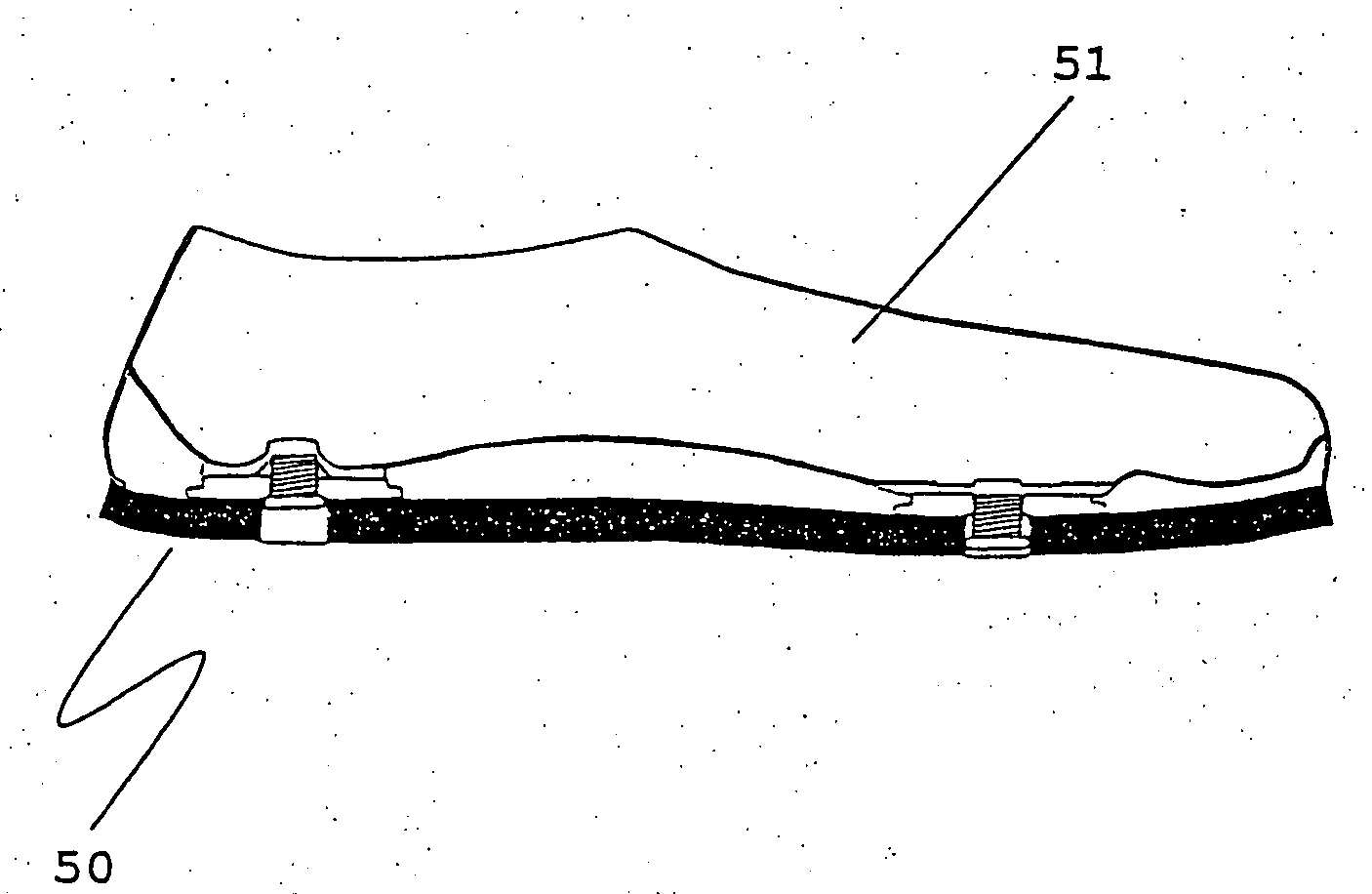
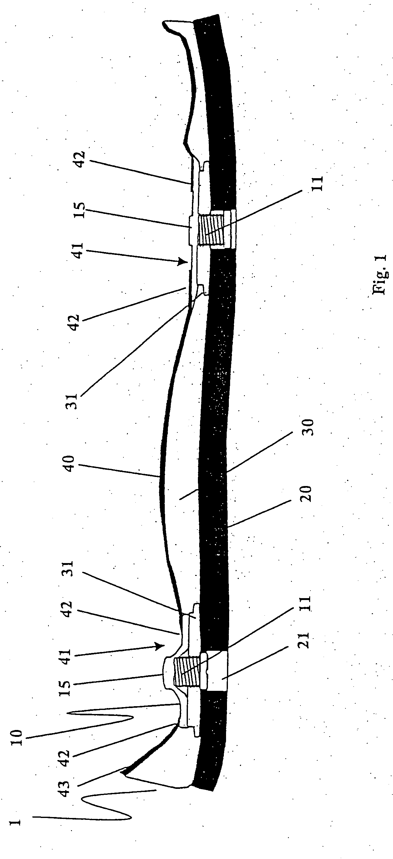
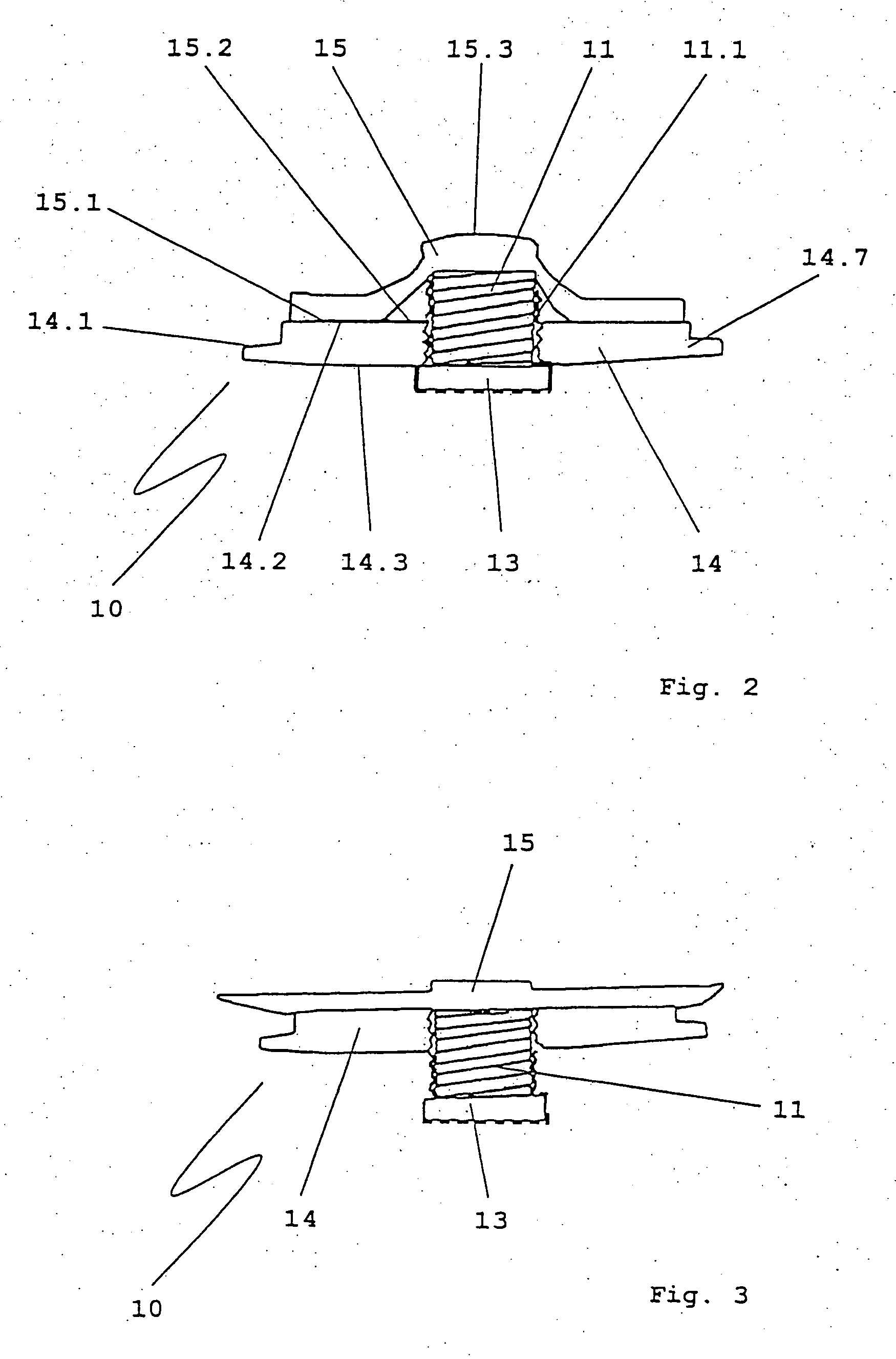
[0061]FIG. 1 shows a section through a shoe sole 1, which has an outsole 20 with apertures 21, a midsole 30 and an insole 40. The insole 40 is adapted in its shape to the midsole 30, which at the same time forms the foot bed 43. Provided in the midsole 30 is a recess, in which a pressure massage element 10 can be integrated. The pressure massage element 10 is connected via the receiving region 31 of the midsole 30 to the latter in the customary way. The pressure massage element 10 is covered over from below by the outsole 20 and is held by the latter. Apertures 41 are provided in the insole 40. These apertures 41 are closed from the side on which the pressure massage element 10 is located by a permanently elastic covering 15 of Sorbothane®. In the region of overlap 42 of the insole 40, the covering 15 of the pressure massage element 10 is covered over by the material of the insole 40. This provides additional cushioning of the foot in this region, both in the active position and in ...


PUM


Abstract

The invention relates to a shoe sole (1) that features a pressure massage function and comprises a bottom outsole (20), a top covering sole (40), and at least one adjustable pressure massage element (10) that is located between the outsole (20) and the covering sole (40). Said pressure massage element (10) is accessible from below through the outsole (20) via a breakthrough (21) in the outsole (20) in order to adjust the pressure massage element (10). The pressure massage element (10) is provided with a bolt (11) which extends perpendicular to the shoe sole (1) and is used for applying the pressure massage to the foot. In order to be able to activate and deactivate the massage function in a simple manner, the bolt (11) is vertically adjustable at least between a lower inactive position and an upper active position in which the bolt (11) causes the covering sole (40) to rise and thus the pressure massage to be applied to the foot.

Description

FIELD OF THE INVENTION[0001]The invention relates generally to a shoe sole with a pressure massage function. In particular, the invention relates to a shoe sole with a pressure massage function with a pressure massage element which is accessible and adjustable from below through an outsole. The invention also relates to a shoe and a sandal.BACKGROUND OF THE INVENTION[0002]Generally, shoe soles are made up of more than one layer comprising at least one lower outsole and an insole. In this case, the insole is in contact with the foot. There is often provided also a mid-sole between the insole and the outsole.[0003]The parts are normally firmly connected to one another, each part having specific adapted properties—adapted for its function and for the area of use of the shoe sole with the resultant requirements. The properties are defined by the selection of the materials used and by the shaping of the parts.[0004]By modification of the construction and by incorporation of additional el...

Claims


Application Information

Patent Timeline
Patent Type & Authority Applications(United States)
IPC IPC(8): A43B3/12A43B13/18A61F5/01
CPCA43B7/1465A43B13/14A61H7/001A61H2205/125A61H2201/1284A61H2201/165A61H39/04A61H2201/1664A43B7/1464
Inventor EBELING, STEPHAN
Owner EBELING STEPHAN
Learn More