
Selectively controlled rocker one-way clutch

a one-way clutch, selective control technology, applied in the direction of mechanical actuated clutches, interengaging clutches, gearing, etc., can solve the problems of excessive internal backlash, limited torque transmitting capacity, and large amount of machining of powder metal components, so as to achieve significant reduction of backlash and facilitate assembly

Active Publication Date: 2008-08-07
FORD GLOBAL TECH LLC
View PDF46 Cites 103 Cited by
  • Summary
  • Abstract
  • Description
  • Claims
  • Application Information

AI Technical Summary

Benefits of technology

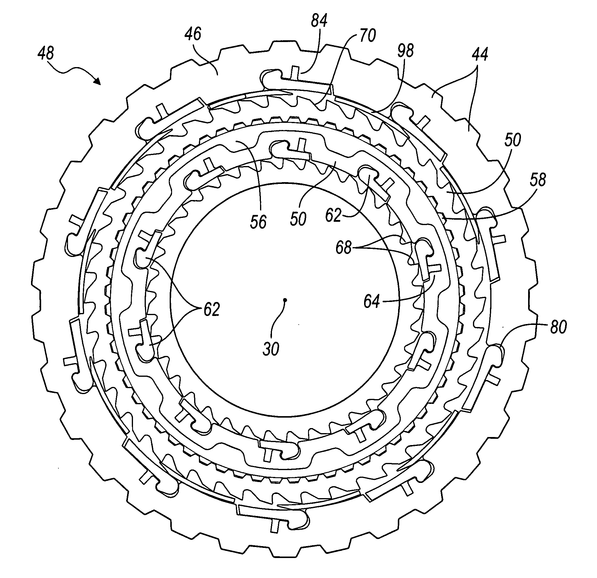
[0013]The shape of a pocket plate, which contains the rockers, requires no secondary machining operations for any purpose, such as to eliminate densifiers and de-densifiers in the powder metal components. The components of the clutch that are formed from powder metal require no machining after they are formed.
[0014]The number of notches for a given diameter is greater than other one-way clutches, thereby significantly reducing backlash. The design lends itself to easy assembly due to its configuration.
[0016]Each pocket is closed at one axial end to provide structural continuity, stiffness and strength to carry forces resulting from engagement of the rockers with the notches when the clutch is engaged.
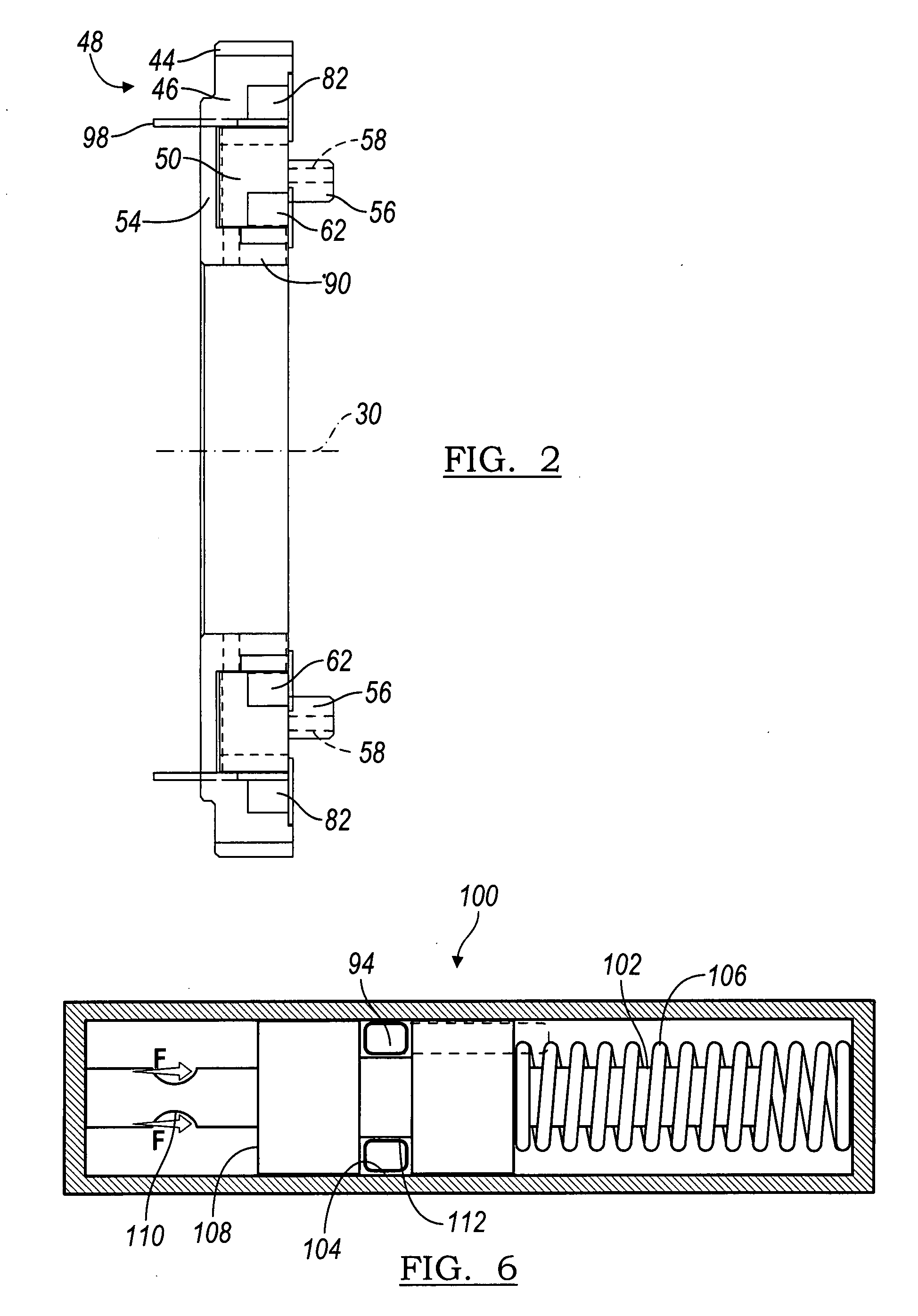
[0017]An actuator, secured to control elements, actuating the control elements to control movement of the rockers. A summing device secured to the actuator can apply a first force representing a first status condition and a second force representing a second status condition. The actuator activates the control elements to prevent engagement of the rockers with the second notches when the first and second forces are concurrently applied to the summing device.

Problems solved by technology

Rocker and sprag type one-way clutch assemblies can increase the torque capacity for a given package size compared to those of a roller-type clutch, but they are generally limited in torque transmitting capacity by the magnitude of the contact or bearing stresses caused by contact of the rockers or sprags with the races.
The clutches described in the '978 or '245 patents, however, require a significant amount of machining of the components that are formed of powder metal.
Excessive internal backlash, which can produce noise at unacceptable levels, is a potentially problem under certain operating conditions with these clutches.

Method used


Image

  • Selectively controlled rocker one-way clutch
  • Selectively controlled rocker one-way clutch
  • Selectively controlled rocker one-way clutch

Examples


Embodiment Construction

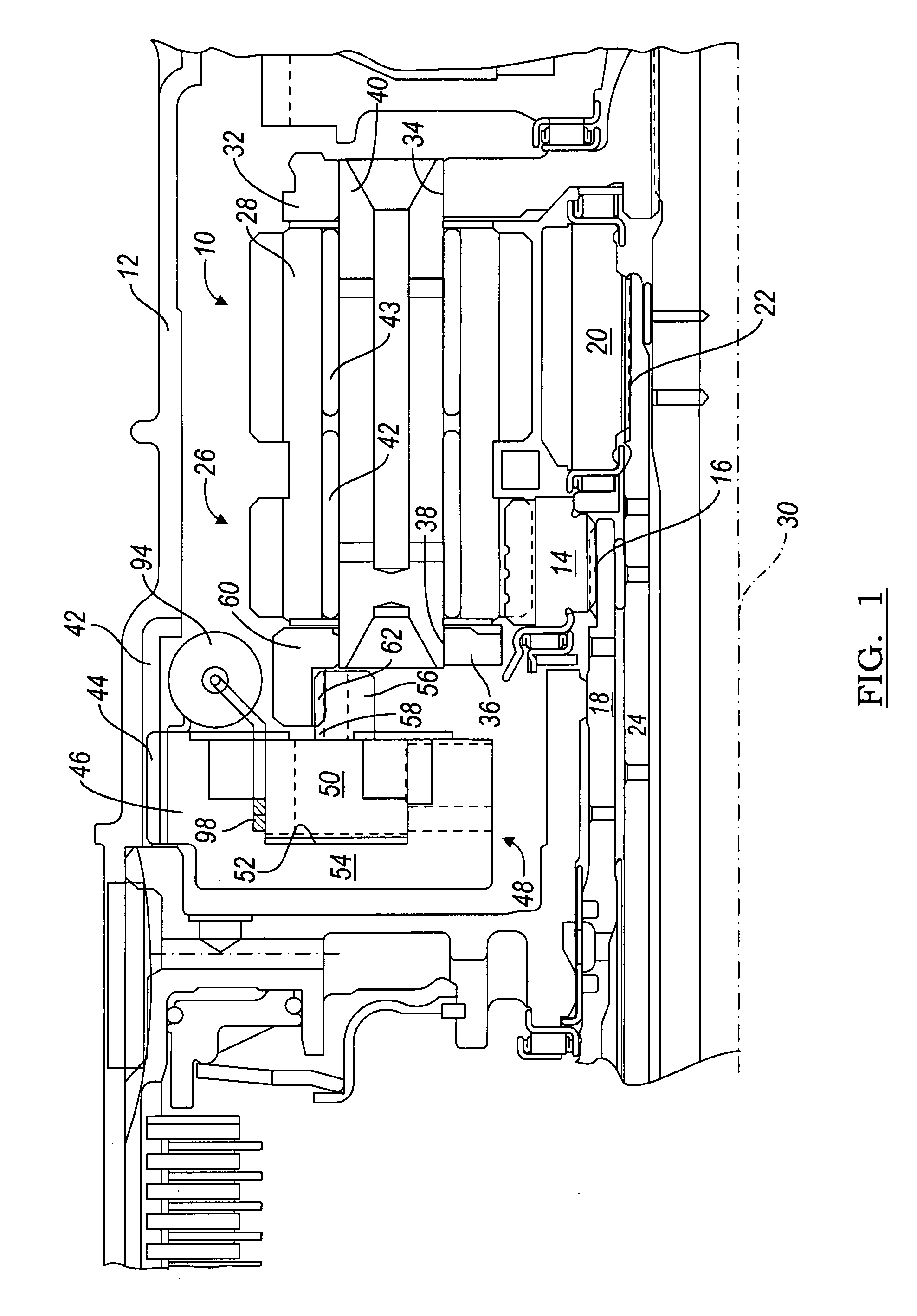
[0027]Referring to FIG. 1, a planetary gear assembly 10 of the Ravigneaux type located in a transmission case 12 includes a first sun gear 12, connected by a spline 16 to a rotating shaft 18; a second sun gear 20, connected by a spline 22 to a rotating shaft 24; a planet pinion carrier assembly 26, which is supported for rotation and includes long planet pinions 28, each spaced angularly about an longitudinal axis 30, supported on the carrier 26 and meshing with sun gear 14. The gear assembly 10 includes a set of short planet pinions (not shown), each spaced angularly about axis 30, supported on carrier 26 and meshing with sun gear 20 and a long pinion 28. The gear assembly 10 further includes a ring gear (not shown) surrounding the long pinions 28, short pinions and sun gears 14, 20 and engaged with the long pinions 28.

[0028]The carrier assembly 26 includes a first disc 32 formed with axial holes 34; a second disc 36 spaced axially from the first disc and formed with axial holes 38...


PUM


Abstract

An overrunning clutch assembly includes a first ring having pockets spaced mutually about an axis, rockers each located in a pocket, springs each urging a rocker to pivot in a respective pocket, and first notches arranged around the axis. A second ring includes second pockets spaced mutually about the axis, second rockers each located in a second pocket such that at least one second rocker is engageable with a notch, second springs each urging a second rocker toward engagement with a notch, and second notches around the axis, at least one rocker being engageable with at least one second notch. A control member moves about the axis alternately to prevent the first rockers from engaging the second notches and to permit the first rockers to engage the second notches.

Description

BACKGROUND OF THE INVENTION[0001]1. Field of the Invention[0002]This invention relates generally to a clutch that produces a drive connection between components when their relative rotation is in one direction, and overruns when relative rotation is in the opposite direction. In particular, the invention pertains to such a one-way or overrunning clutch having rockers, which engage and disengage in response to selectable actuation.[0003]2. Description of the Prior Art[0004]Conventional one-way clutches for producing a one-way drive connection between inner and outer races of the clutch include sprags or rollers for driveably connecting the races and the components of a mechanical assembly connected to the races. Such clutches are commonly used in the powertrain or driveline of an automotive vehicle. One-way clutches perform satisfactorily in many cases, but certain applications, such as those in which large magnitudes of torque are transmitted by the clutch, or those that provide onl...

Claims


Application Information

Patent Timeline
Patent Type & Authority Applications(United States)
IPC IPC(8): F16D41/12
CPCF16D41/084F16H57/08F16H3/66F16D41/12F16D41/16F16D11/16
Inventor KIMES, JOHN W.
Owner FORD GLOBAL TECH LLC
Learn More