Apparatus and method for providing pointing capability for a fixed camera

a technology of fixed cameras and apparatuses, applied in the field of cameras, can solve the problems of limited payload capability, large physical dimension of the focal plane electronics and lenses, and relatively heavy ir camera, and achieve the effects of small size, limited payload capability, and low weigh

Inactive Publication Date: 2008-08-07
HONEYWELL INT INC
View PDF10 Cites 39 Cited by
  • Summary
  • Abstract
  • Description
  • Claims
  • Application Information

AI Technical Summary

Benefits of technology

[0016]A primary advantage of the present invention is its low weight, enabling its installation on a small UAV with limited payload capability.
[0017]Another advantage of the present invention is its small size, so that it will not significantly increase the size of the UAV and not interfere with its aerodynamics.
[0018]Yet another advantage is the low power consumption because high power consumption requires a large battery that adds to the UAV payload.
[0019]Another advantage of the present invention is that it can also be used in ground-based surveillance applications, and due to the small size of the invention, it improv...

Problems solved by technology

However, an IR camera is relatively heavy and the physical dimension of its focal plane electronics and lens are quite large compared to the size of a vehicle as small ...

Method used


Image

  • Apparatus and method for providing pointing capability for a fixed camera
  • Apparatus and method for providing pointing capability for a fixed camera
  • Apparatus and method for providing pointing capability for a fixed camera

Examples


Embodiment Construction

Best Modes For Carrying Out the Invention

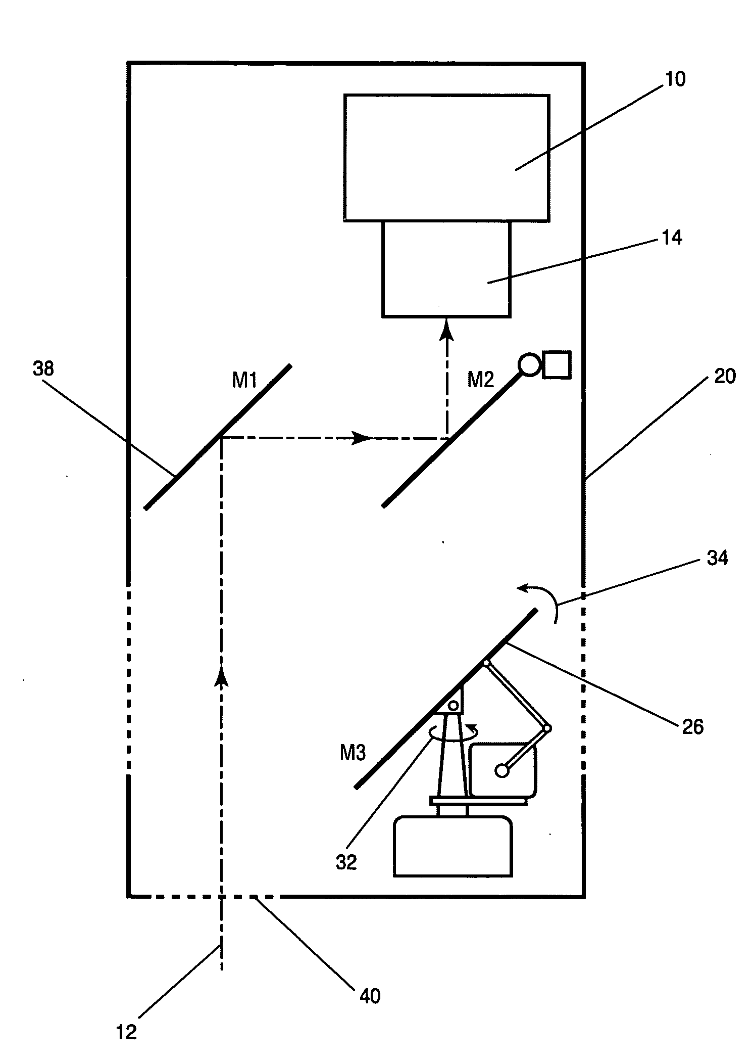
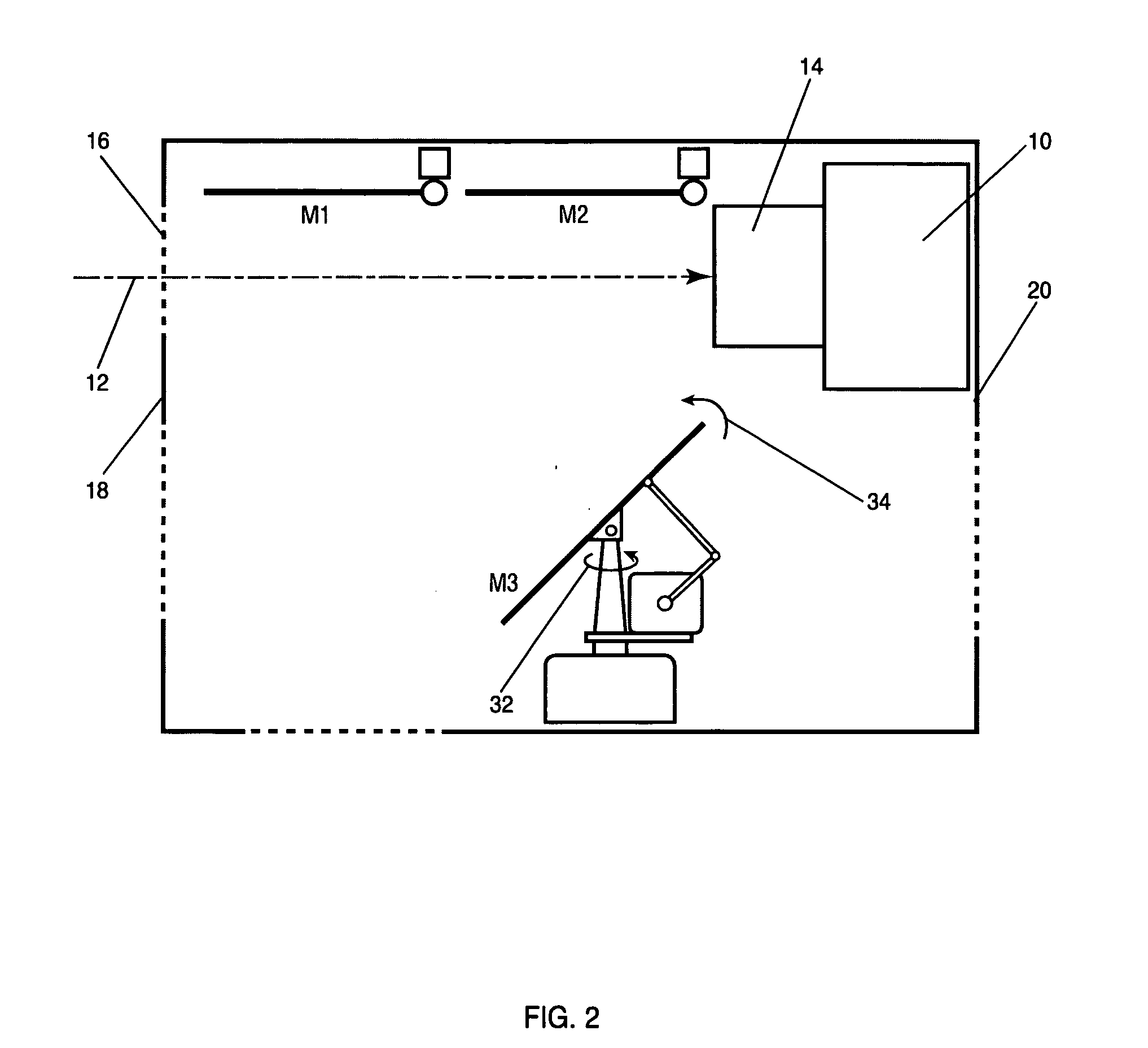
[0031]The present invention is a method and apparatus for providing a camera viewing area for a camera mounted in a UAV such as a vertical take off and landing MAV. Four embodiments that illustrate the use of the present invention are described. Although the following descriptions are for IR cameras, the present invention can be used with all other types of cameras, thus this disclosure is not limited to IR cameras. The first embodiment is shown in FIGS. 2, 3, and 4. FIG. 2 shows an IR camera 10 mounted horizontally in a payload canister 20 that is attached to the MAV. Target image 12 enters camera lens 14 through a left upper IR-transparent window 16 on the left side 18 of canister 20. This is a mode of operation where camera 10 is in fixed forward-looking position and the image quality is optimal because image 12 is not reflected off mirrors. FIG. 3 shows a pan-tilt mode of operation of the first embodiment. IR reflective mirror M222 is til...


PUM


Abstract

Reflective movable mirrors are used to reflect an image from a desired direction into the lens of a camera. This apparatus is preferably used with infrared (IR) cameras. To capture images from different directions, the orientations of the mirrors are modified. The mirrors are light, requiring only miniature motors and actuators for moving them. The mirrors are also much smaller than the focal plane electronics and the IR lens, requiring much less space for moving them than would be required for moving the camera. This provides a pointing capability for an airframe-fixed IR camera and this capability is provided with minimum additional payload, space and power requirements. The apparatus and method can be used for IR and electro-optical (EO) cameras.

Description

CROSS-REFERENCE TO RELATED APPLICATIONS[0001]This application is based on U.S. Provisional Application Ser. No. 60 / 716,208 entitled “Apparatus and Method for Providing Pointing Capability for Fixed Camera”, filed on Sep. 12, 2005, the teachings of which are incorporated herein by reference.BACKGROUND OF THE INVENTION[0002]1. Field of the Invention (Technical Field)[0003]The present invention relates to cameras and more particularly to controlling the viewing direction such as pan and tilt angles, of a camera with extreme weight, size, and power restrictions.[0004]2. Background Art[0005]The present invention solves the problem where a pan-tilt mechanism must be extremely light and small, because it is intended for a very small unmanned air vehicle (UAV). It must also consume little electrical power to maximize battery life. Presently, pan-tilt units for cameras are known standard devices that one can purchase. However, these units are large, heavy and consume significant electrical p...

Claims


Application Information

Patent Timeline
IPC IPC(8): G01J5/02G02B5/08
CPCG01J5/08G01J5/0809G01J5/084H04N7/185G02B26/0816G02B26/101H04N5/2259G01J5/0893G01J5/0808H04N23/58
Inventor HORAK, DAN T.GOOSSEN, EMRAY R.MARTINEZ, STEVEN D.
Owner HONEYWELL INT INC
Why Eureka
Try Eureka