
Apparatus and method for ranging

Inactive Publication Date: 2008-08-07
ORMON CORP
View PDF9 Cites 30 Cited by
  • Summary
  • Abstract
  • Description
  • Claims
  • Application Information

AI Technical Summary

Benefits of technology

[0011]This allows fast-response distance measurement and relative-velocity measurement even if an object comes within close range.
[0017]This reduces the load on the calculation control means due to such determination, allowing simplification of the structure of the calculation control means and reduction of cost.
[0019]This eliminates the need for the related-art amplifier gain control that has been triggered when an object comes within close range.
[0021]This reduces the load on the calculation control means due to such determination, allowing simplification of the structure of the calculation control means and reduction of cost.
[0029]As described above, the invention allows distance measurement and / or relative-velocity measurement, and more particularly, allows fast-response distance measurement even if an object comes within close range.

Problems solved by technology

However, sensors using fast Fourier transform (FFT) analysis such as the related-art two-frequency CW radar have the problem of low responsiveness because the analysis takes much time.
Therefore, the related-art sensors cannot sufficiently meet the above-described requirement if another vehicle (object) comes closer than a predetermined range.

Method used


Image

  • Apparatus and method for ranging
  • Apparatus and method for ranging
  • Apparatus and method for ranging

Examples


Embodiment Construction

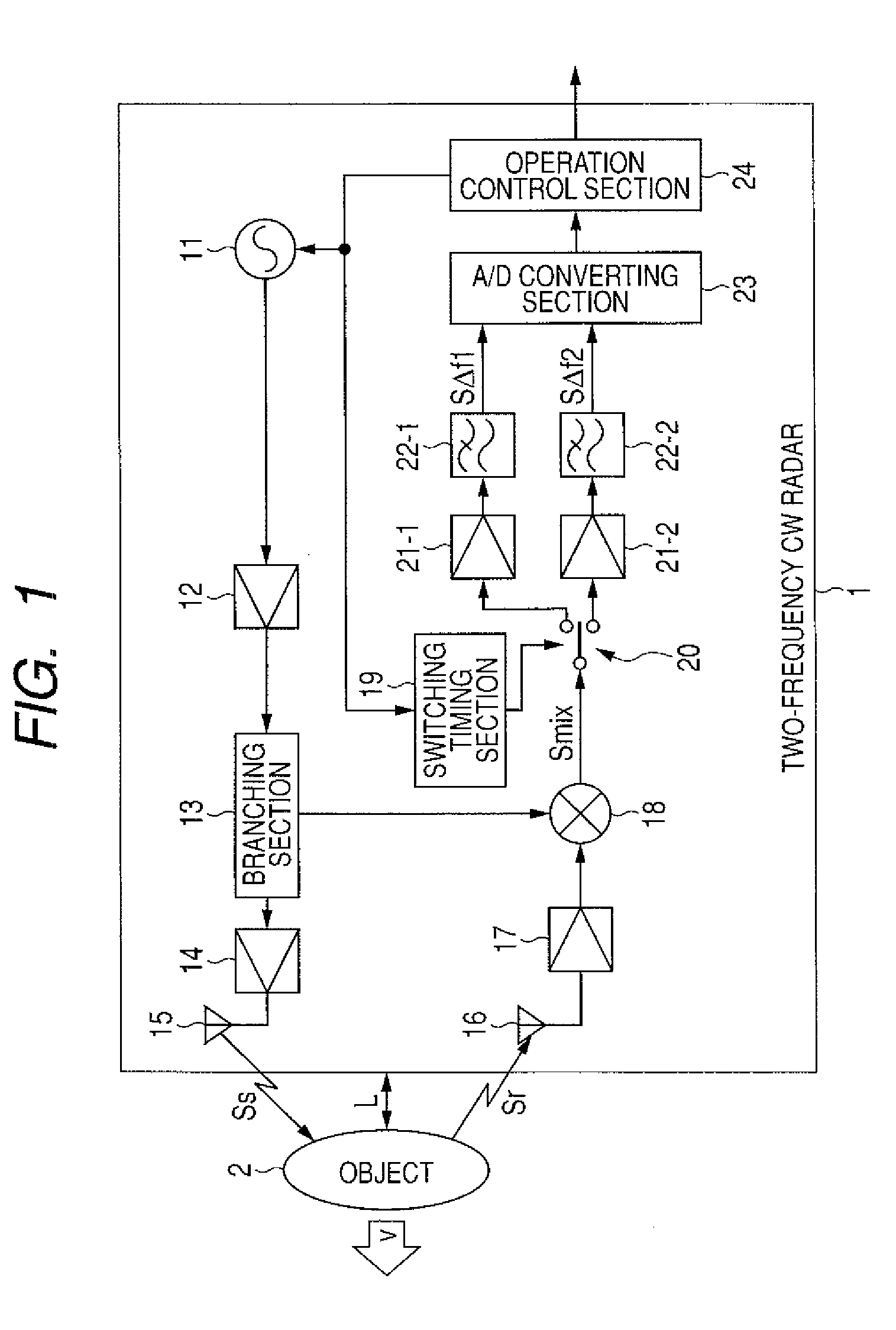
[0043]FIG. 1 is a block diagram of a measuring apparatus according to an embodiment of the invention.

[0044]The measuring apparatus of FIG. 1 is a two-frequency CW radar 1.

[0045]The two-frequency CW radar 1 can perform measurement by two-frequency CW method as the name suggests.

[0046]The outline of the two-frequency CW measurement will be described hereinbelow.

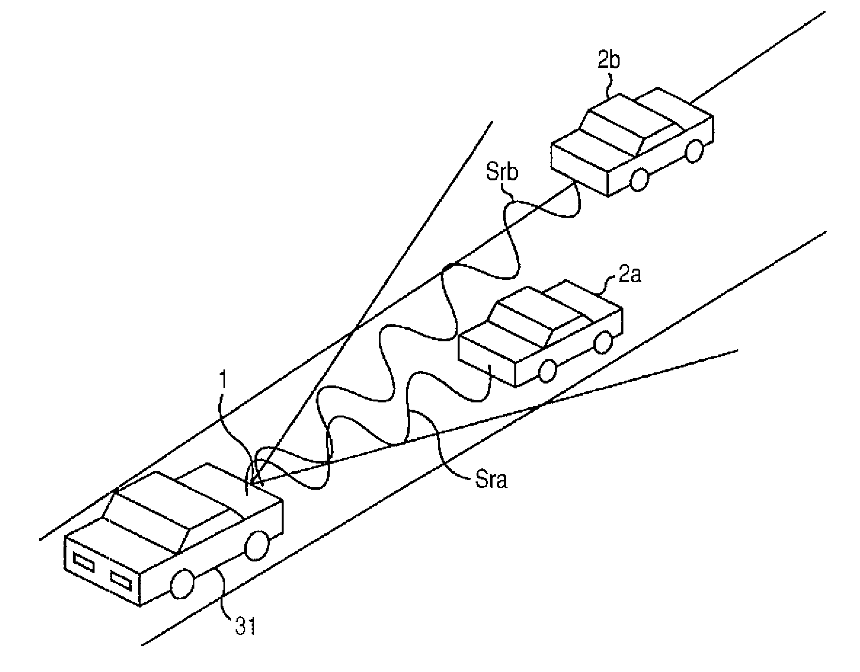
[0047]The two-frequency CW radar 1 generates a signal in which two different waves (CWs) with a frequency f1 and a frequency f2 are switched by time division (hereinafter, referred to as a two-frequency CW) and outputs the two-frequency CW as a transmission signal Ss.

[0048]The transmission signal Ss is reflected by an object 2 and received as a reception signal Sr by the two-frequency CW radar 1.

[0049]Assume relative velocity v is present between the two-frequency CW radar 1 and the object 2, Doppler frequencies Δf1 and Δf2 are generated in the frequencies f1 and f2 of the transmission signal Ss, respectively, so that the frequ...


PUM


Abstract

The measurement of the distance or / and the relative velocity with fast response is to be achieved while the accuracy of measurement of the distance to an object in close range is maintained. A calculation-execution determination section determines whether or not an object is present within a predetermined range from the strength of a two-frequency Doppler signal sent from an A / D converting section and past calculated distance sent from a calculation selecting section. If the object is outside the predetermined range, the distance calculated by an FFT-method calculating section is output from a calculation output section via an calculation selecting section. If the object is within the predetermined range, one of the distance calculated by a time-interval-method calculating section and the distance calculated by the FFT-method calculating section is selected by the calculation selecting section, and is output from the calculation output section. The invention can be applied to a fast response system such as a precrash system.

Description

BACKGROUND OF THE INVENTION[0001]1. Field of the Invention[0002]The present invention relates to an apparatus and a method for measuring the distance or the relative velocity to an object, and more particularly, to an apparatus and a method for measuring the distance or / and the relative velocity with fast response even if an object comes within close range.[0003]2. Description of Related Art[0004]Known sensors for measuring the relative velocity or distance between a host vehicle and another vehicle include a continuous wave (CW) radar, an FMCW radar, and a two-frequency continuous wave (CW) radar (hereinafter, referred to as a two-frequency CW radar) (refer to Japanese Patent No. 3203600 and JP-A-2004-69693 (Patent Documents 1 and 2)). Among them, the two-frequency CW radar measures the relative velocity and the distance to another vehicle by detecting the frequency (hereinafter, referred to as a Doppler frequency) or the phase of the Doppler signal of a signal reflected by the obj...

Claims


Application Information

Patent Timeline
IPC IPC(8): G01S13/00G01S13/931
CPCG01S13/347G01S13/348G01S13/38G01S2013/9375G01S13/931G01S2013/9321G01S13/584G01S2013/93271
Inventor ICHIYANAGI, HOSHIBUMITAKENOUCHI, SHINYASATOH, YASUHIRONUMATA, HIROYUKI
Owner ORMON CORP
Learn More