Bubble micro-pump and two-way fluid-driving device, particle-sorting device, fluid-mixing device, ring-shaped fluid-mixing device and compound-type fluid-mixing device using the same

a micro-pump and two-way technology, applied in the direction of machines/engines, positive displacement liquid engines, transportation and packaging, etc., can solve the problems of micro-fluidic systems pumps require complicated control signals, pumps also subject to many restrictions of technology

Inactive Publication Date: 2008-08-07
QISDA CORP
View PDF40 Cites 13 Cited by
  • Summary
  • Abstract
  • Description
  • Claims
  • Application Information

AI Technical Summary

Problems solved by technology

However, if the micro-fluidic systems are configured with complicated mechanical components that have strict dimensional specifications, the micro-fluidic systems are subjected to many restrictions of technology.
However, such pumps require complicated controlling signals and need to install a sensor in the micro-fluidic systems for detecting the properties of the fluid.
The pumps are also subjected to many restrictions of technology.

Method used


Image

  • Bubble micro-pump and two-way fluid-driving device, particle-sorting device, fluid-mixing device, ring-shaped fluid-mixing device and compound-type fluid-mixing device using the same
  • Bubble micro-pump and two-way fluid-driving device, particle-sorting device, fluid-mixing device, ring-shaped fluid-mixing device and compound-type fluid-mixing device using the same
  • Bubble micro-pump and two-way fluid-driving device, particle-sorting device, fluid-mixing device, ring-shaped fluid-mixing device and compound-type fluid-mixing device using the same

Examples


first embodiment

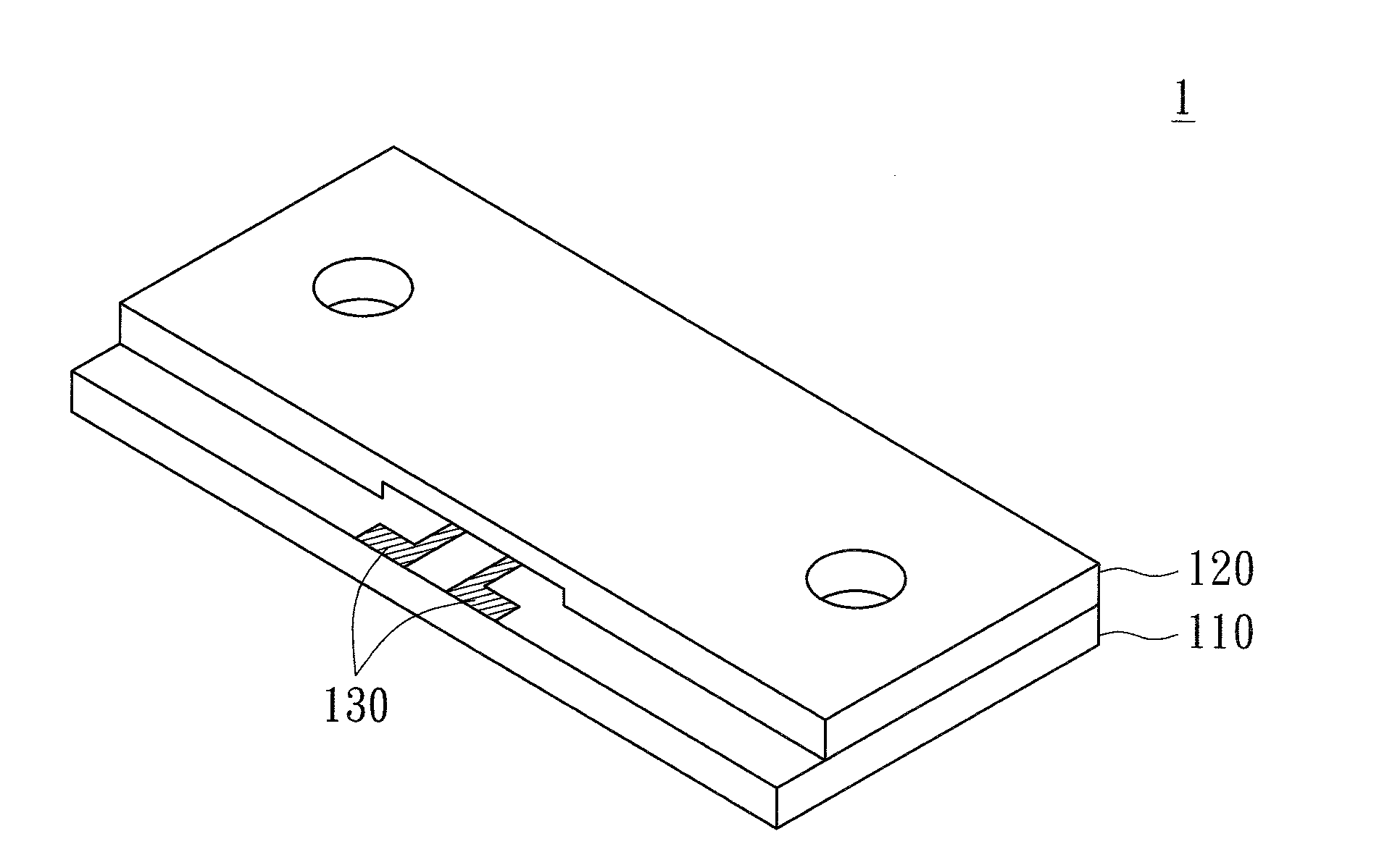
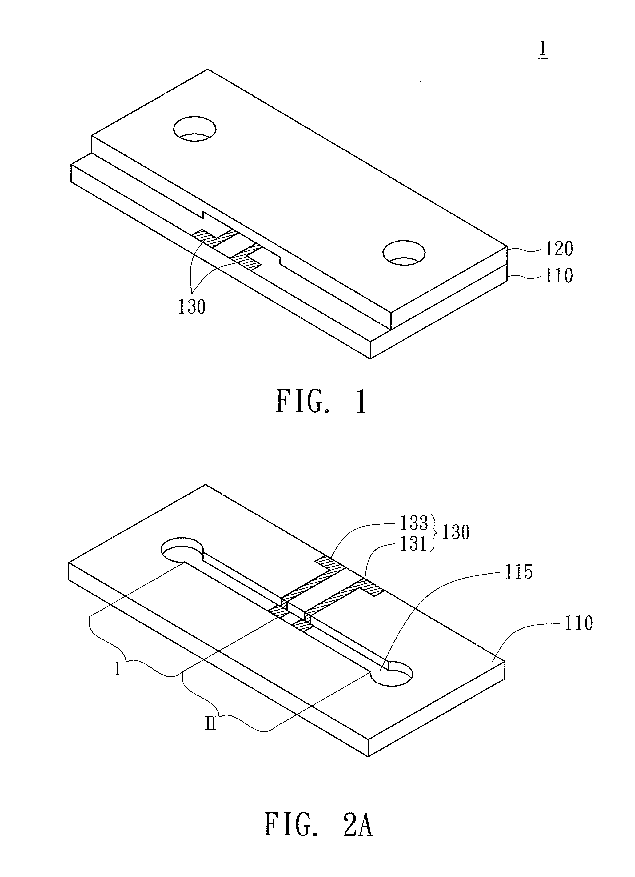
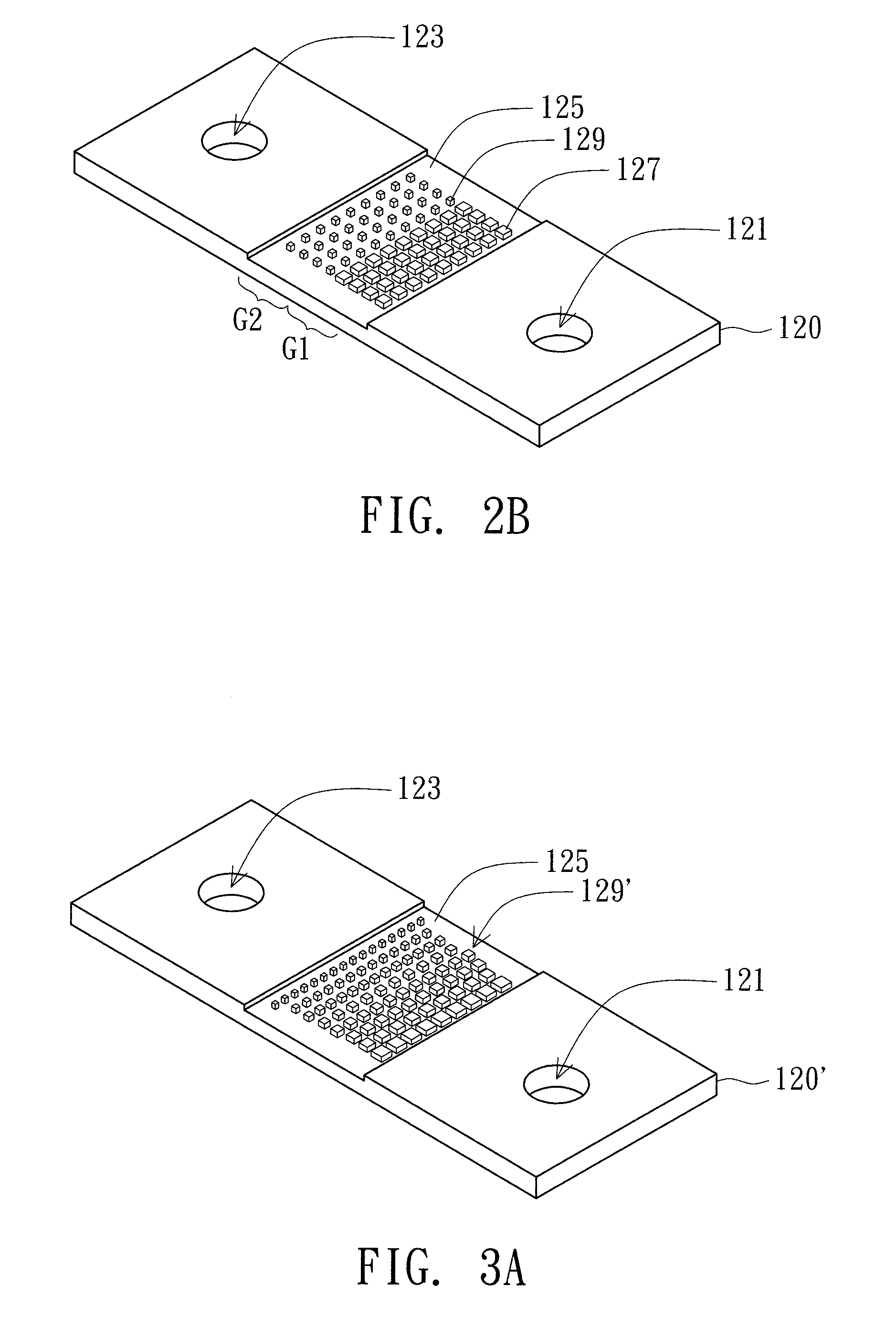
[0036]Referring to FIG. 1, a perspective of a bubble micro-pump according to a first embodiment of the invention is shown. As indicated in FIG. 1, the bubble micro-pump 1 includes a first component 110, a second component 120 and a bubble-generating unit 130. The second component 120 is disposed above the first component 110. The bubble-generating unit 130 is disposed above the first component 110. An air is generated between the first component 110 and the second component 120 when a fluid fills the vacancy between the first component 110 and the second component 120. Referring to FIGS. 2A-2B, FIG. 2A is a perspective of a first component of the bubble micro-pump of FIG. 1, and FIG. 2B is a first perspective of a second component of the bubble micro-pump of FIG. 1. As indicated in FIG. 2A, the first component 110 includes a flow path 115, and the flow path 115 has at least a first area I and a second area II. Preferably, the bubble-generating unit 130 is disposed in accordance with...

second embodiment

[0053]The second embodiment provides a two-way fluid-driving device that controls the flowing direction of the fluid through the use of different flow paths.

[0054]Referring to FIG. 8, a perspective of a two-way fluid-driving device according to the second embodiment of the invention is shown. As indicated in FIG. 8, the two-way fluid-driving device 200 includes a first primary flow path 210, a second primary flow path 220, a first driving portion 230, a second driving portion 240 and a controlling unit 250. The first primary flow path 210 and the second primary flow path 220 are alternately disposed to form a common flow path area II. The first driving portion 230 disposed on the first primary flow path 210 is adjacent to the common flow path area III, and the second driving portion 240 disposed on the second primary flow path 220 is also adjacent to the common flow path area III. The first driving portion 230 and the second driving portion 240 are driven by the bubble micro-pump of...

third embodiment

[0058]Referring to FIG. 11, a first perspective of a particle-sorting device according to a third embodiment of the invention is shown. As indicated in FIG. 11, the particle-sorting device 300 includes a primary flow path 310, a driving portion 320, a diversion portion 330, a detecting unit 340 and a controlling unit 350. The driving portion 320 is disposed at the front part of the primary flow path 310. The diversion portion 330 includes a first branch flow path 331 and a second branch flow path 335, and is connected with the rear part of the primary flow path 310. A bubble micro-pump 333 similar to the micro-pump 1 of the first embodiment is disposed on the first branch flow path 331, and a bubble micro-pump 337 is disposed on the second branch flow path 335. The detecting unit 340 disposed on primary flow path 310 is located between the driving portion 320 and the diversion portion 330. The controlling unit 350 is electrically connected with the driving portion 320, the bubble mi...


PUM


Abstract

A bubble micro-pump includes a first component, a second component and a bubble-generating unit. The first component includes a flow path having a first area and a second area. The second component above the first component has a first roughness surface and a second roughness surface. The first roughness surface opposite the first area has a first roughness factor, and the second roughness surface opposite the second area has a second roughness factor smaller than the first roughness factor. The bubble-generating unit on the first component generates bubble in the first area and the second area when a fluid fills the vacancy between the first component and the second component. Due to the difference in roughness factor, the backfilling velocity of the fluid in the first area is faster than that in the second area when the bubble starts to vanish, such that the fluid is driven to flow.

Description

[0001]This application claims the benefits of Taiwan application Serial No. 96104350, filed Feb. 6, 2007, and Taiwan application Serial No. 96124835, filed Jul. 6, 2007, the subject matters of which are incorporated herein by reference.BACKGROUND OF THE INVENTION[0002]1. Field of the Invention[0003]The invention relates in general to a bubble micro-pump, and more particularly to a low power-consumption bubble micro-pump and two-way fluid-driving device, a particle-sorting device, a fluid-mixing device, a ring-shaped fluid-mixing device and a compound-type fluid-mixing device using the same.[0004]2. Description of the Related Art[0005]In the field of micro-electromechanically system, micro-pumps can be divided into two categories. Examples of the first category, which drives the fluid by mechanical components of the pump, include bubble pump, membrane pump, and diffuser pump. Such pumps have a blade structure, and the components of the pumps are capable of moving. However, if the mic...

Claims


Application Information

Patent Timeline
Patent Type & Authority Applications(United States)
IPC IPC(8): B01F13/00B01F3/08B01F15/02F04B17/00
CPCB01F5/10B01F11/0071F04B19/24F04B17/00F04B19/006B01F13/0059B01F25/50B01F31/65B01F33/30
Inventor LIU, CHENG-HSIENHSU, LONGCHENG, CHIH-MINGCHIU, SHENG-HUNGWANG, WAI WILLIAMCHOU, CHUNG-CHENG
Owner QISDA CORP
Why Eureka
Try Eureka