
Moving image encoding device and moving image encoding method

a moving image and encoding technology, applied in the field of moving image encoding device and moving image encoding method, can solve problems such as increasing encoding volume, and achieve the effects of reducing the magnitude of data to be processed, reducing the processing volume, and reducing the data volume of original image and reference imag

Inactive Publication Date: 2008-08-07
OKI ELECTRIC IND CO LTD
View PDF4 Cites 12 Cited by
  • Summary
  • Abstract
  • Description
  • Claims
  • Application Information

AI Technical Summary

Benefits of technology

The present invention is a moving image encoding device that reduces data volumes of an original image and a reference image while retaining their characteristics. The device includes an image data reduction section, a weighting estimation section, a motion vector search section, a motion compensation section, and a second weighting estimation section. The device uses a weighted reference image generated by applying a weight and an offset to a reference image. The device accurately finds motion vectors using a weighted motion vector search, resulting in smaller differences between a weighted motion-compensated image and the original image. This reduces processing requirements and processing time. The device also uses a least squares method to improve the precision of weighting estimations. Overall, the invention improves the accuracy and efficiency of moving image encoding.

Problems solved by technology

However, a problem arises if a distribution of x[i] and y[i] is not along a line passing through the origin point. FIG. 5 shows an example thereof.
Thus, there is a problem in that encoding volumes increase regardless of time being taken specifically for calculating weightings.

Method used


Image

  • Moving image encoding device and moving image encoding method
  • Moving image encoding device and moving image encoding method
  • Moving image encoding device and moving image encoding method

Examples


first embodiment

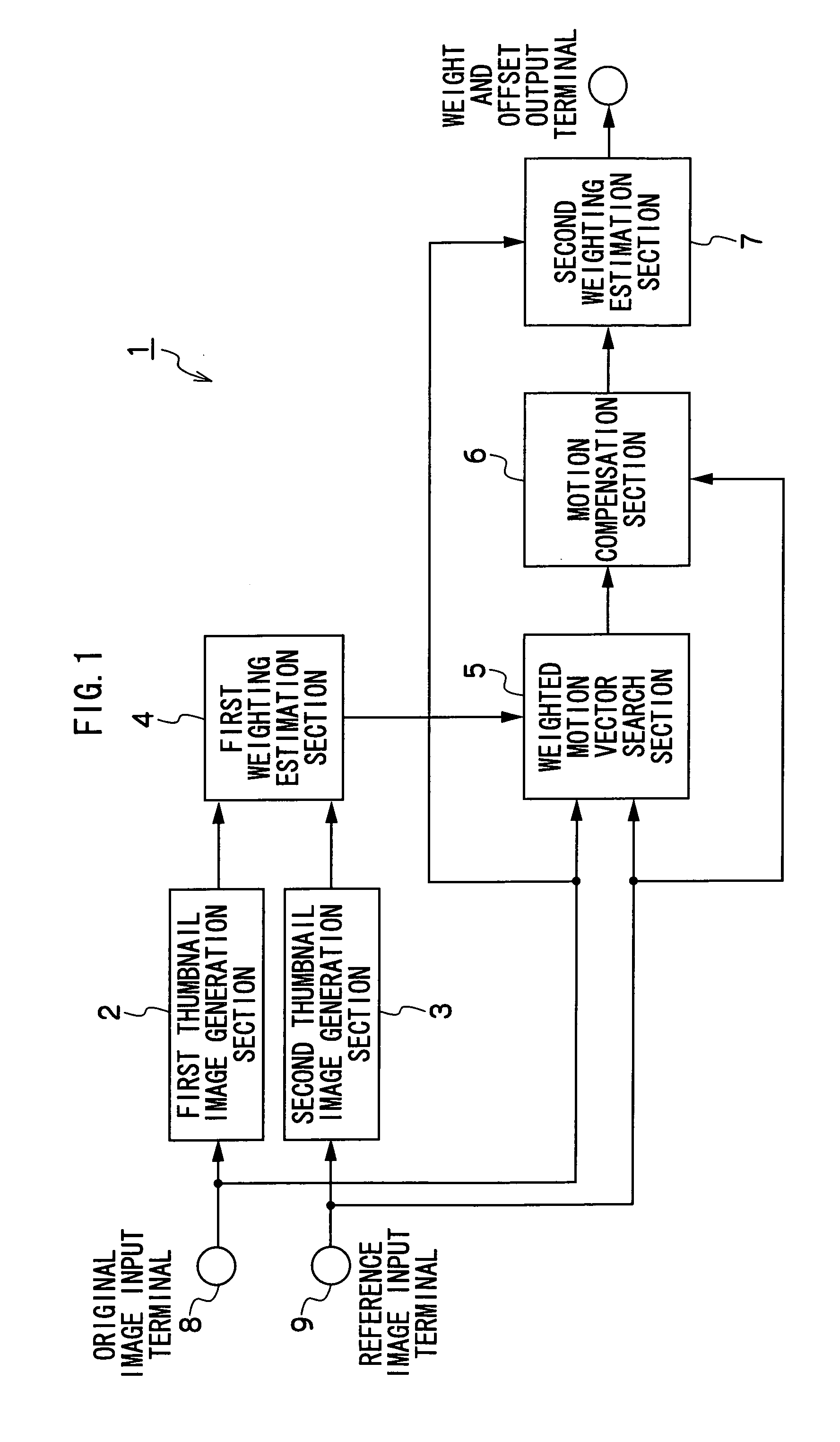
[0033]The moving image encoding device and moving image encoding method relating to the first embodiment will be described on the basis of FIG. 1. The moving image encoding device and moving image encoding method relating to the present embodiment, when an original image and a reference image are inputted, ultimately output a weight and an offset.

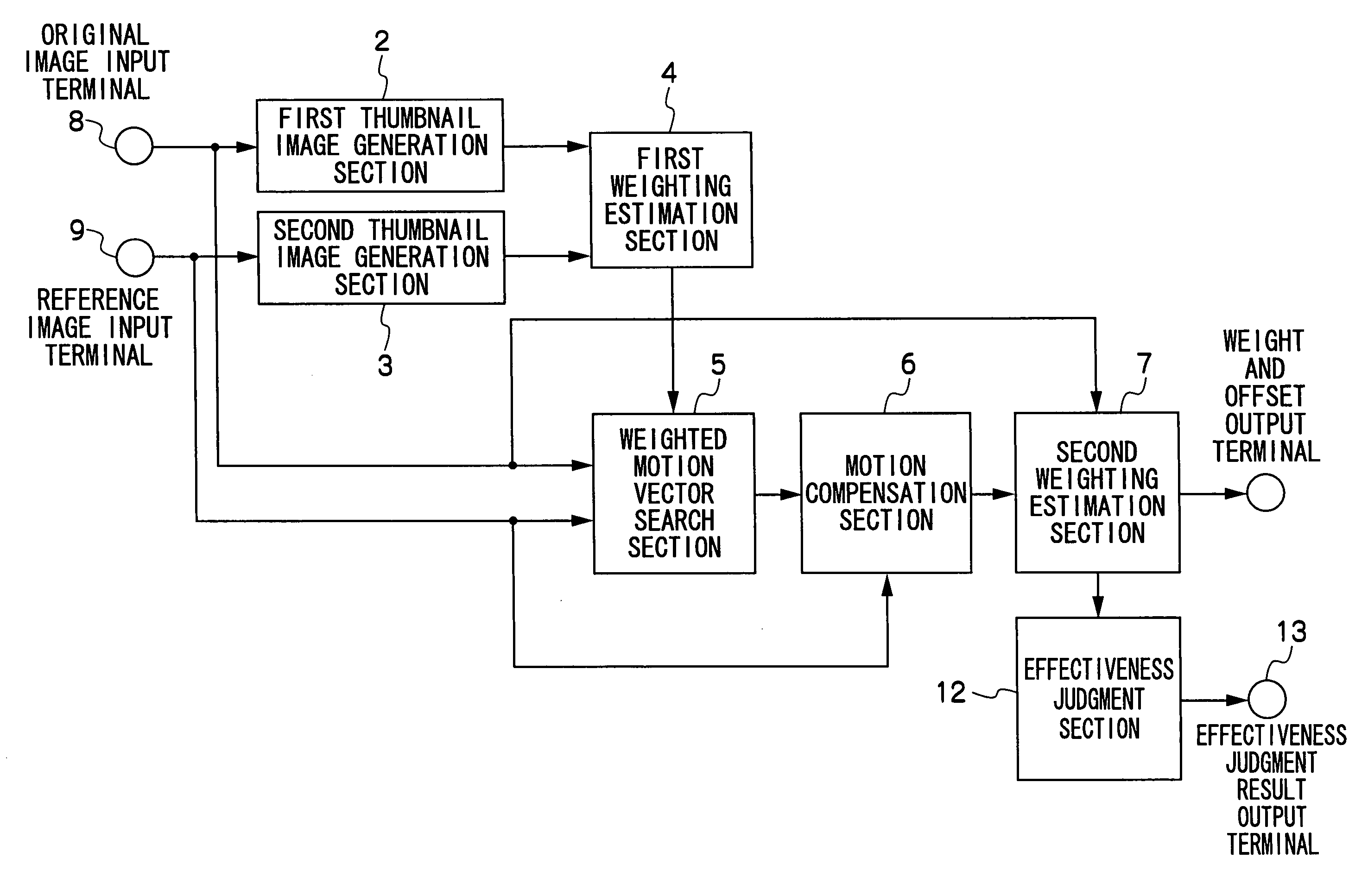
[0034]A moving image encoding device 1 is structured with a first thumbnail image generation section 2, a second thumbnail image generation section 3, a first weighting estimation section 4, a weighted motion vector search section 5, a motion compensation section 6 and a second weighting estimation section 7. Herebelow, structures of the sections will be described in accordance with a sequence in which image data is inputted thereto.

[0035]A compression object original image is inputted through an original image input terminal 8 to the first thumbnail image generation section 2. The first thumbnail image generation section 2 is an image data...

second embodiment

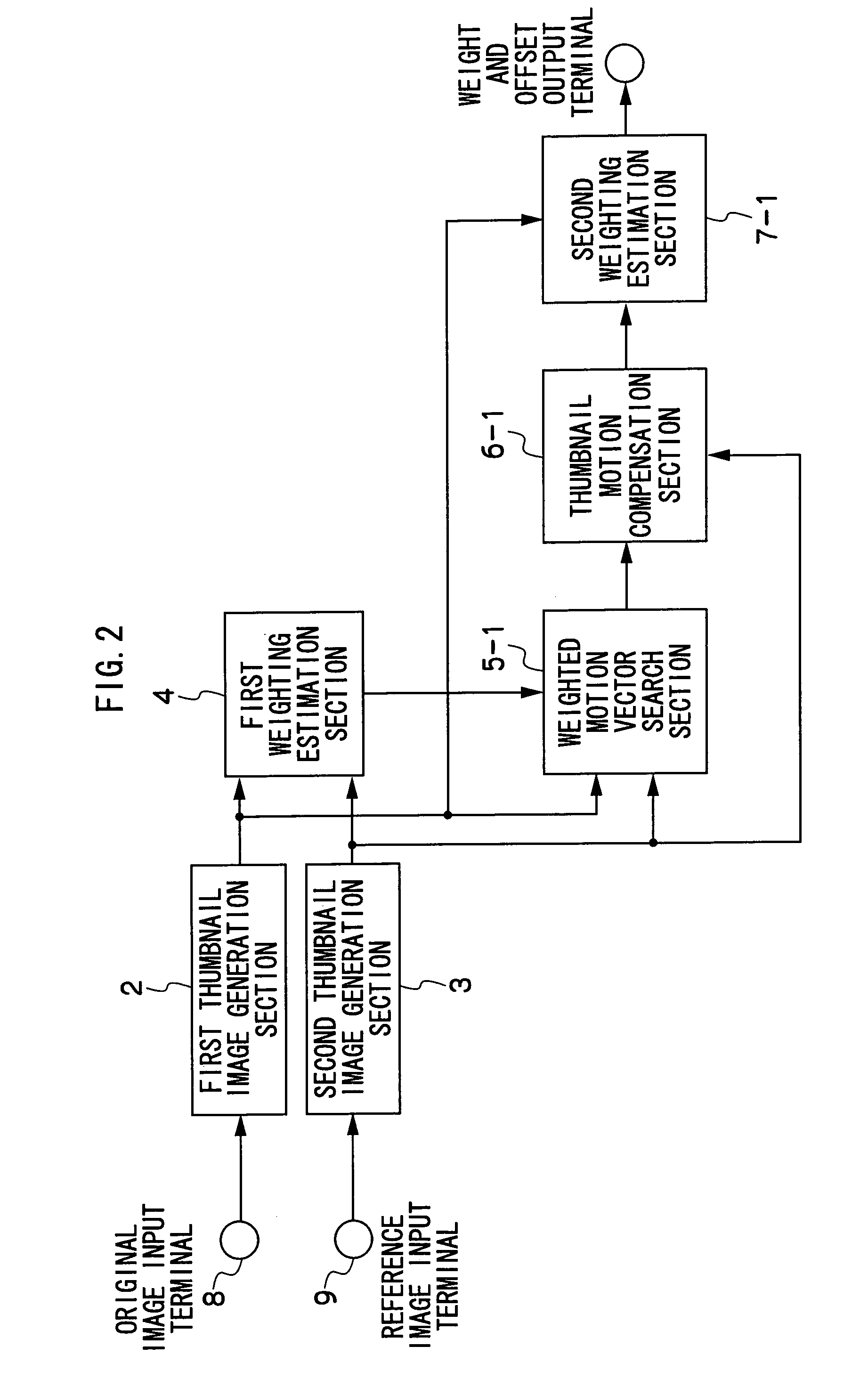
[0079]Next, the moving image encoding device and moving image encoding method of the second embodiment will be described. In the present embodiment, inputs and outputs at the weighted motion vector search section 5, the motion compensation section 6 and the second weighting estimation section 7 differ from the first embodiment. Details of the present embodiment will be described below on the basis of FIG. 2. The moving image encoding device and moving image encoding method of the present embodiment, when an original image and a reference image are inputted, ultimately output a weight and an offset, similarly to the moving image encoding device and moving image encoding method of the first embodiment. Structure will be described in accordance with FIG. 2, in a sequence from the input side.

[0080]Similarly to the first embodiment, the original image input terminal 8 and the reference image input terminal 9 input a compression object original image and a reference image to be used durin...

third embodiment

[0111]Next, the moving image encoding device and moving image encoding method of the third embodiment will be described using FIG. 3. Structure of the present embodiment adds a third thumbnail image generation section 11 to the first embodiment. Accordingly, inputs to the second weighting estimation section 7 differ from the first embodiment.

[0112]Below, differences from the first embodiment will be described.

[0113]The third thumbnail image generation section 11 receives the motion-compensated image which is the output from the motion compensation section 6 and generates a thumbnail image thereof. Output thereof is outputted to the second weighting estimation section 7.

[0114]In the first embodiment, input of the original image to the second weighting estimation section 7 is implemented, but in the third embodiment, the thumbnail original image which is the output from the first thumbnail image generation section 2 is inputted instead. Therefore, in the third embodiment, there is no ...


PUM


Abstract

A moving image encoding device that encodes a difference between a predicted image and an original image is provided. The predicted image is generated using a weighted reference image, for which a weight is multiplied with and an offset is added to a reference image. The moving image encoding device includes an image data reduction section and a weighting estimation section. The image data reduction section reduces data volumes of the original image and the reference image while retaining characteristics of the original image and the reference image. The weighting estimation section estimates weighting parameters on the basis of image data of the original image and reference image of which the data volumes have been reduced by the image data reduction section.

Description

CROSS-REFERENCE TO RELATED APPLICATION[0001]This application claims priority under 35 USC 119 from Japanese Patent Application No. 2007-027032, the disclosure of which is incorporated by reference herein.BACKGROUND OF THE INVENTION[0002]1. Field of the Invention[0003]The present invention relates to a moving image encoding device and a moving image encoding method that perform encoding of a moving image using interframe differences.[0004]2. Description of the Related Art[0005]In a moving image encoding system that encodes differences between a predicted image and an original image, as a technology which applies a weight and adds an offset to a predicted image, and a technology which takes differences from the original image and encodes the same, there are technologies such as that illustrated in Japanese National Publication No. 2006-509467.[0006]In Japanese National Publication No. 2006-509467, if pixel values of an original image are X[i], and pixel values of a predicted image are...

Claims


Application Information

Patent Timeline
Patent Type & Authority Applications(United States)
IPC IPC(8): H04N7/32H04N19/137H04N19/105H04N19/196H04N19/50H04N19/503H04N19/51H04N19/90
CPCH04N19/51H04N19/105
Inventor TOKUMITSU, MASAYUKINAKAGAWA, SATOSHI
Owner OKI ELECTRIC IND CO LTD
Learn More