Fuel Cell Structure and Method of Manufacturing Same

a fuel cell and electrolyte technology, applied in the manufacture of final products, cell components, electric/magnetic/electromagnetic heating, etc., can solve the problem of insufficient improvement, and achieve the effect of reducing manufacturing costs, improving gas dispersibility, and greatly simplifying the manufacturing process

Inactive Publication Date: 2008-08-07
HORI MASARU +2
View PDF9 Cites 5 Cited by
  • Summary
  • Abstract
  • Description
  • Claims
  • Application Information

AI Technical Summary

Benefits of technology

The present technology allows for easier production of cells with different structures like pore size or patterns on their surface while maintaining good electrical conductivity. This results from making these materials smaller than traditional methods that require multiple steps during fabrication processes. Additionally, this integration improves the efficiency at producing high power density electrochemically active components (PECs).

Problems solved by technology

The technical problem addressed in this patent is to increase the electric conductivity of the catalyst layer in polymer electrolyte fuel cells and to improve the generation efficiency of the fuel cell. The conventional electrodes for fuel cells have low electron conductivity, resulting in decreased fuel cell efficiency. This patent proposes an electrode structure with a conductive porous material as the current collector and a catalyst layer made of carbon nanofiber and a proton conductor formed on the surface of the carbon nanofiber in contact with the electrode catalyst particle.

Method used


Image

  • Fuel Cell Structure and Method of Manufacturing Same
  • Fuel Cell Structure and Method of Manufacturing Same
  • Fuel Cell Structure and Method of Manufacturing Same

Examples


example 1

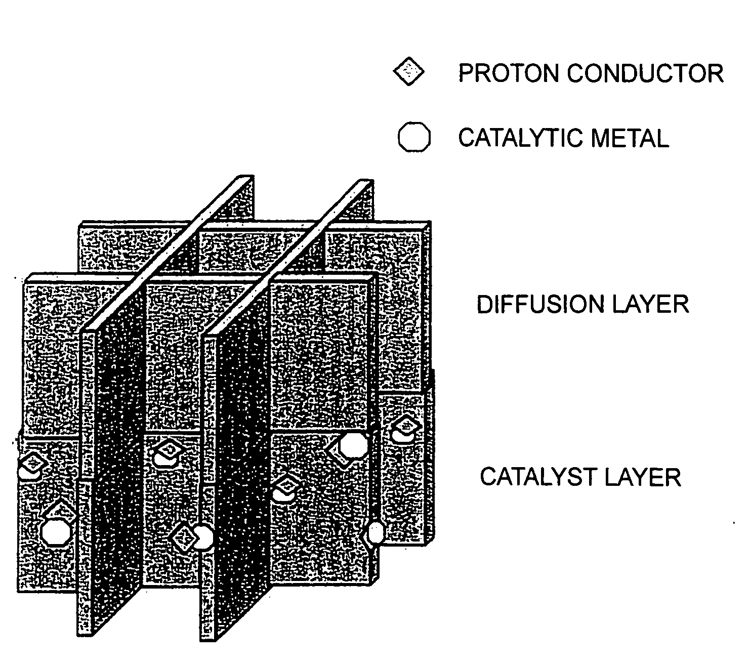
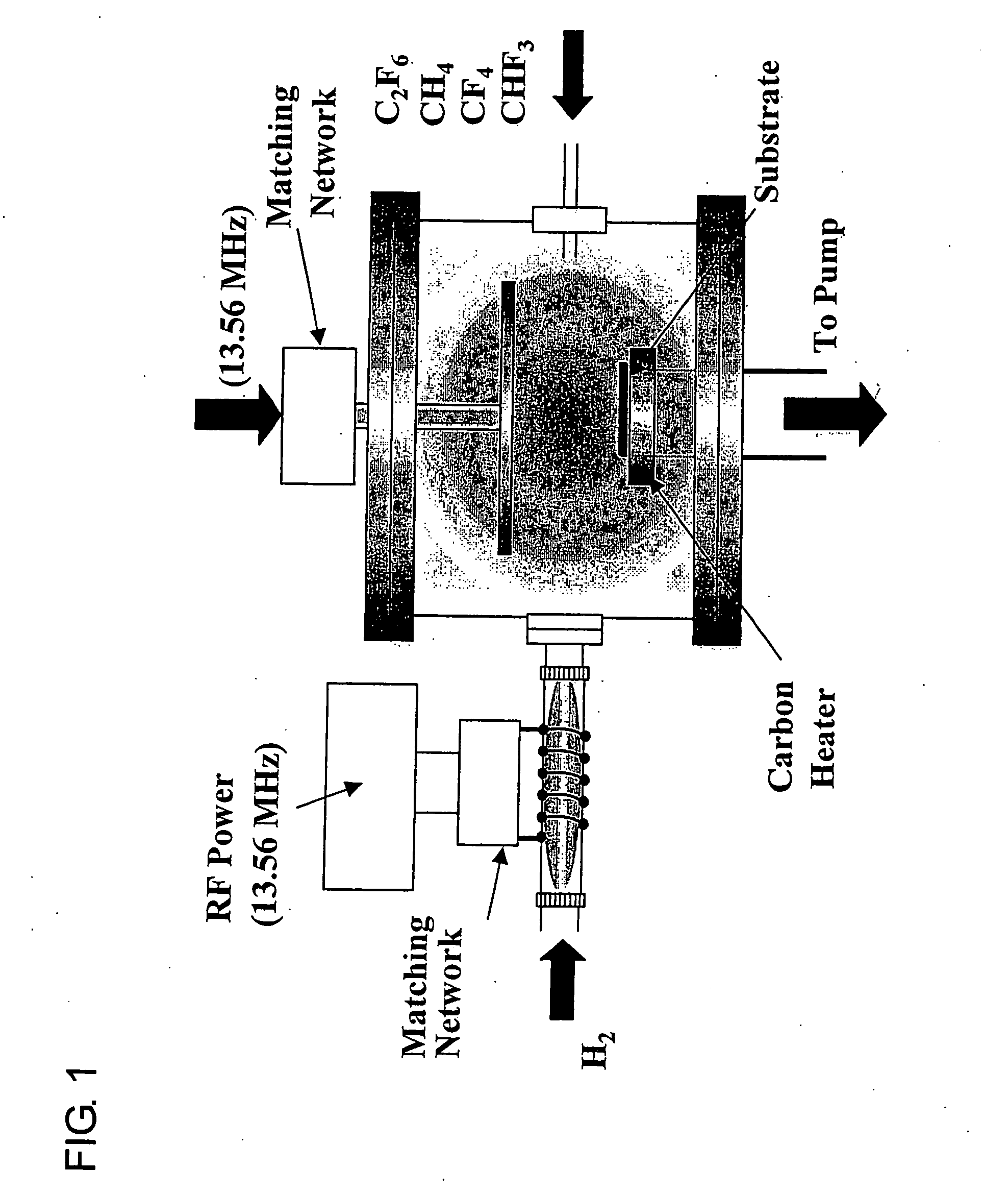
[0045]A process is described for manufacturing a diffusion layer-catalyst layer integrated thin-film using a diffusion layer-catalyst layer one-step manufacturing method shown in FIG. 6. In the present example, CNW is used for both the diffusion layer and the catalyst layer. First, using a plasma CVD apparatus shown in FIG. 6, CNW is manufactured on a separator as the diffusion layer. Thereafter, the manufacturing conditions are modified and CNW is manufactured, while at the same time the CNW surface is modified with a catalyst component and an electrolyte by means of laser, arc discharge, or plasma. In this way, a diffusion layer-catalyst layer integrated thin-film is completed. Conversely, it is also possible to manufacture a catalyst layer from the side of the electrolyte and to fabricate the diffusion layer finally. The proton conductor consists of a substance having a sulfonate group, phosphonate group, hydroxyl group, imidazole group, solid acid salt, tropolone, ionic liquid, ...

example 2

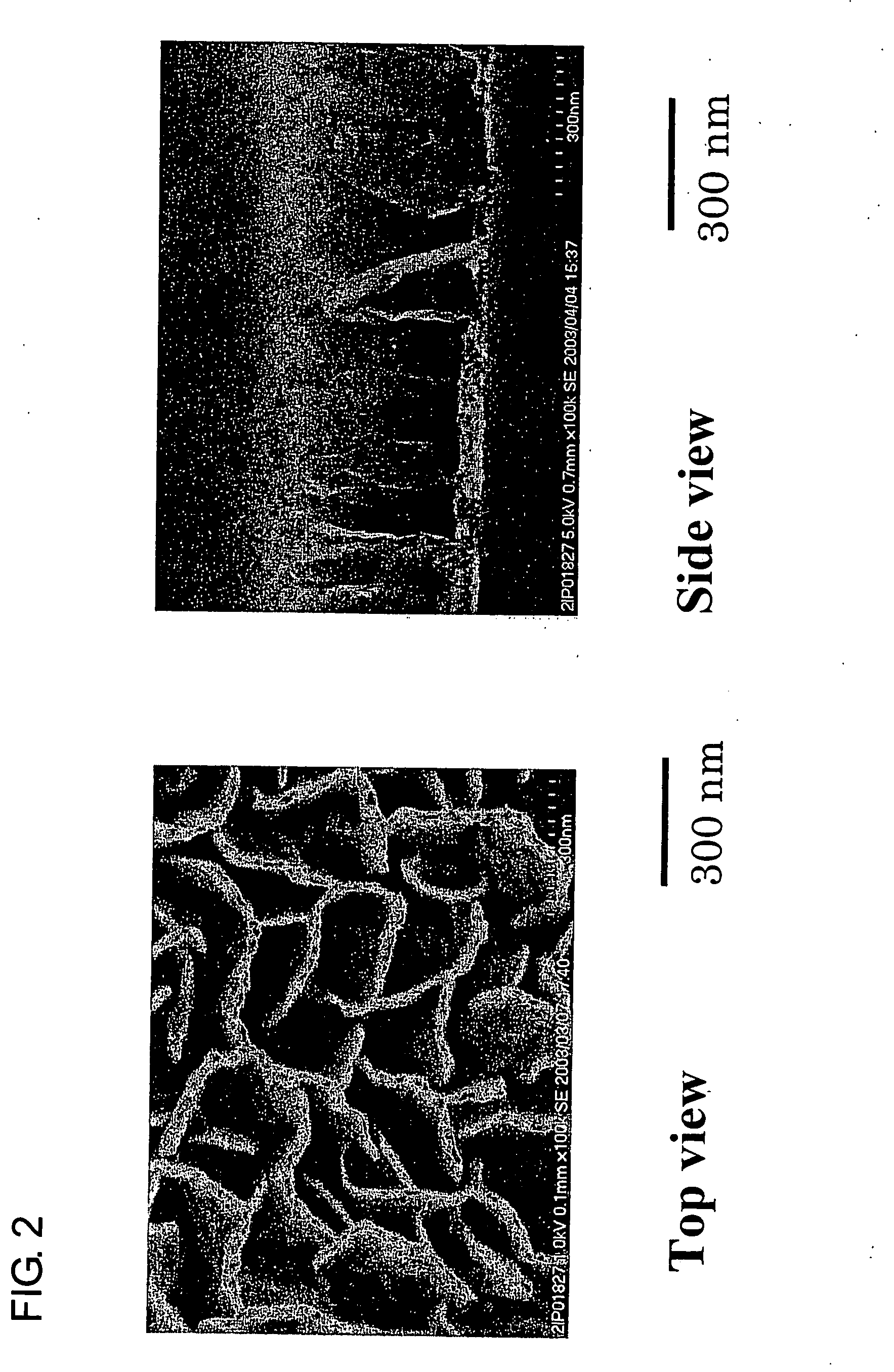
[0046]FIG. 7 shows an example of a method of providing openings by plasma etching. In this method, metal nanoparticles are deposited on the surface of CNW by means of arc discharge or plasma discharge, for example. The amount of deposit in this case is such that the CNW is visible. Thereafter, the CNW alone is etched, thereby providing nano-size through-holes. For example, by exposing the CNW of FIG. 7 in oxygen plasma, etching only proceeds in the portions of the gaps between the metal fine particles, so that through-holes are provided at those portions.

[0047]In accordance with Examples 1 and 2, the following advantages can be obtained: (1) since the diffusion layer-catalyst layer integrated thin-film can be formed at once in the same chamber, the number of steps can be reduced and therefore cost can be reduced; and (2) since the diffusion layer-catalyst layer is continuously formed, there is no contact resistance, whereby electricity generation loss in the fuel cell can be reduced...


PUM

PropertyMeasurementUnit
Electrical conductivityaaaaaaaaaa
Structureaaaaaaaaaa
Efficiencyaaaaaaaaaa

Abstract

A fuel cell structure comprises a diffusion layer and/or a catalyst layer which are made of a carbonaceous porous material having a nano-size structure, such as carbon nanowall (CNW). A method of manufacturing the structure is also disclosed. The structure and method simplify the process of manufacturing a fuel cell electrode comprised of an electrode catalyst layer and a gas diffusion layer. The electrical conductivity of the catalyst layer is increased and the diffusion efficiency of the diffusion layer is improved, whereby the electricity generation efficiency of the fuel cell can be improved.

Description


Claims


Application Information

Patent Timeline
Owner HORI MASARU
Why Eureka
Try Eureka