Pattern forming apparatus and method

a technology of pattern forming and forming apparatus, which is applied in the direction of microlithography exposure apparatus, printers, instruments, etc., can solve the problems of low productivity and complexity of digital exposure apparatus, and achieve the effect of high productivity and simplified apparatus structur

Inactive Publication Date: 2008-08-07
FUJIFILM CORP
View PDF3 Cites 11 Cited by
  • Summary
  • Abstract
  • Description
  • Claims
  • Application Information

AI Technical Summary

Benefits of technology

[0030]Accordingly, a structure of the apparatus can be simplified at the same with high productivity, because the first and second periods are determined for alternate transport of plural boards in one transport path.

Problems solved by technology

However, there is a problem in a long takt time required for each one of boards, to result in a low productivity.
There is a problem of complexity of the digital exposure apparatus in JP-A 2005-037914 due to requirement of a structure for preventing interference between the movable stages on the transport path.

Method used


Image

  • Pattern forming apparatus and method
  • Pattern forming apparatus and method
  • Pattern forming apparatus and method

Examples


Embodiment Construction

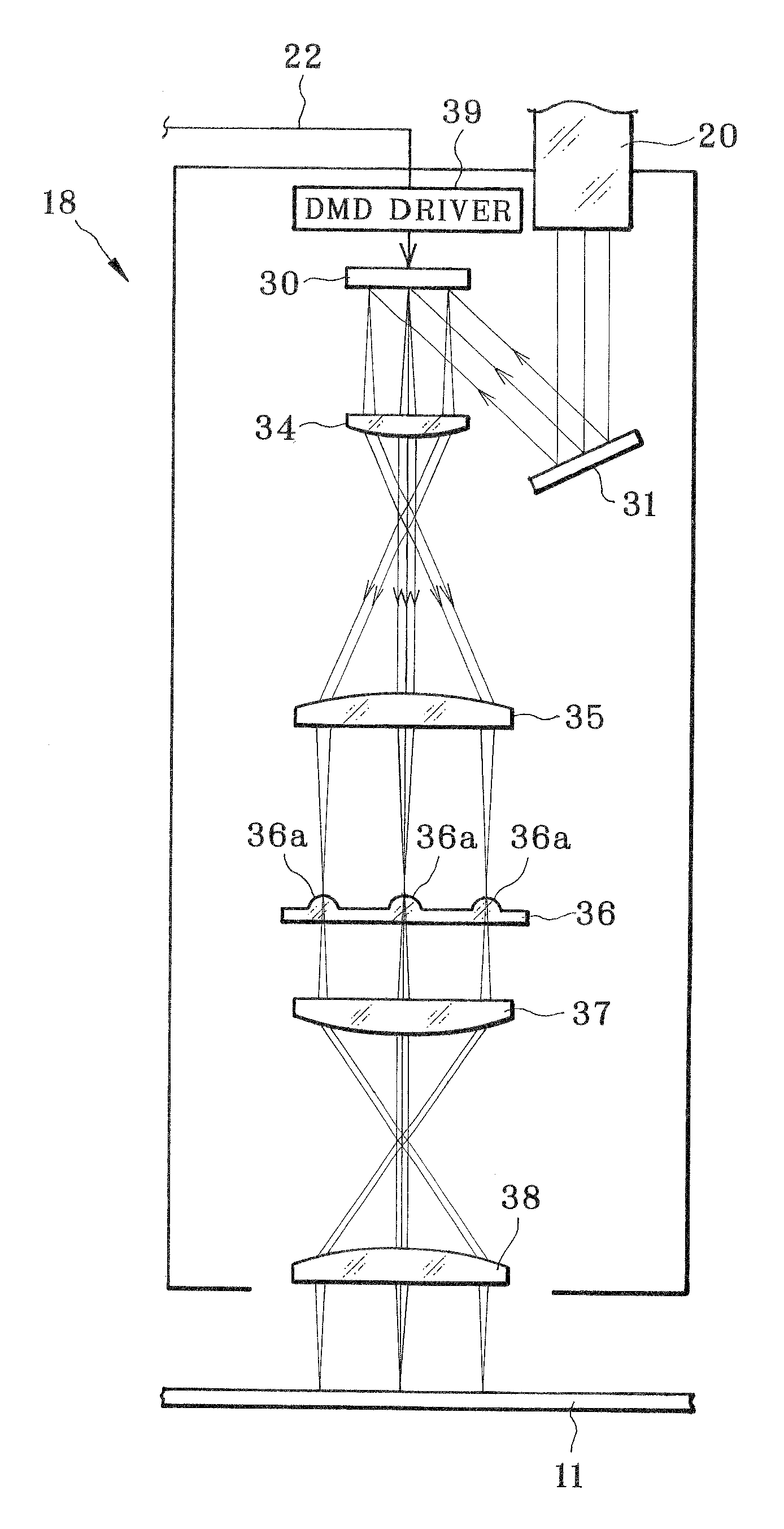
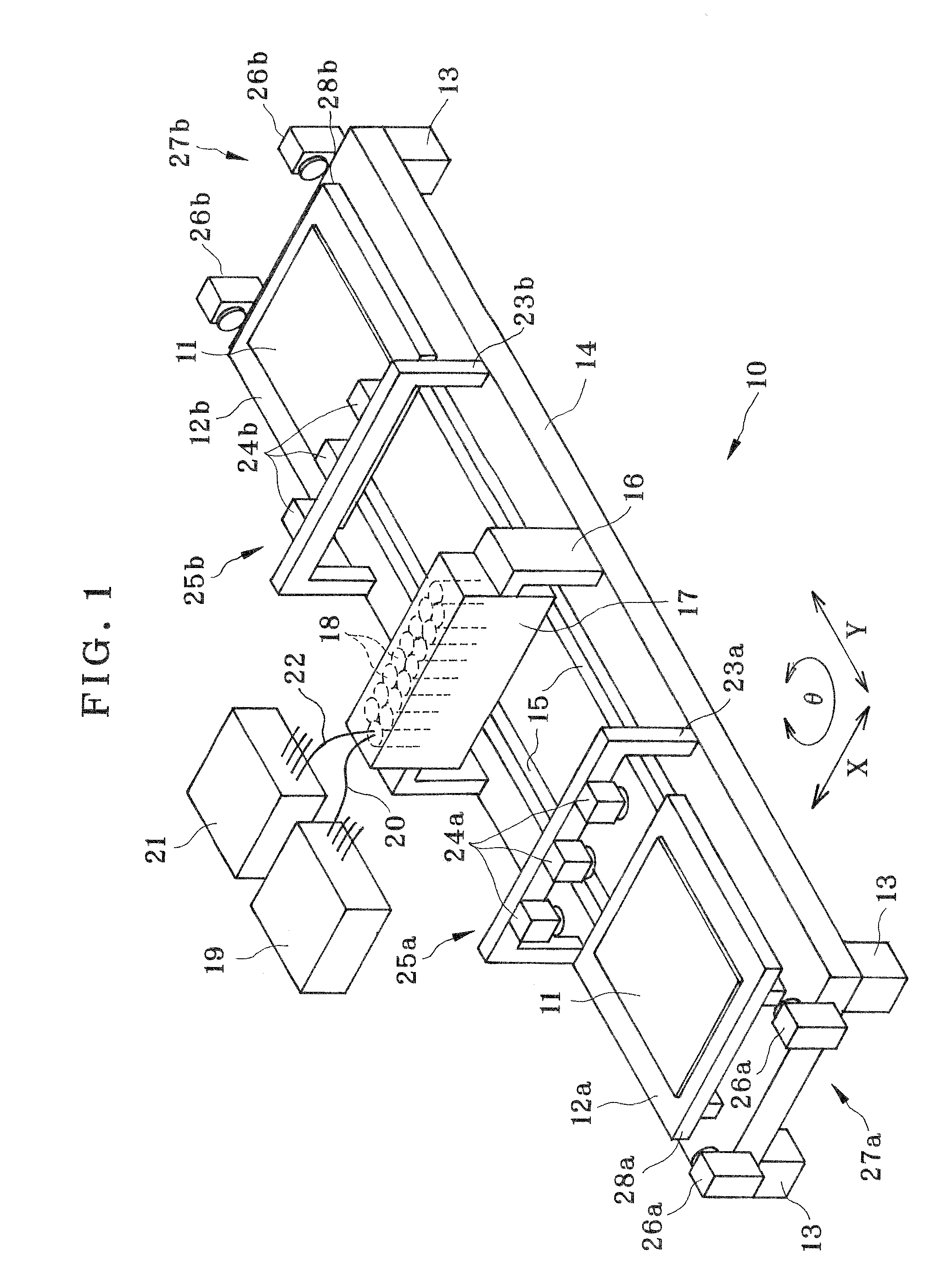
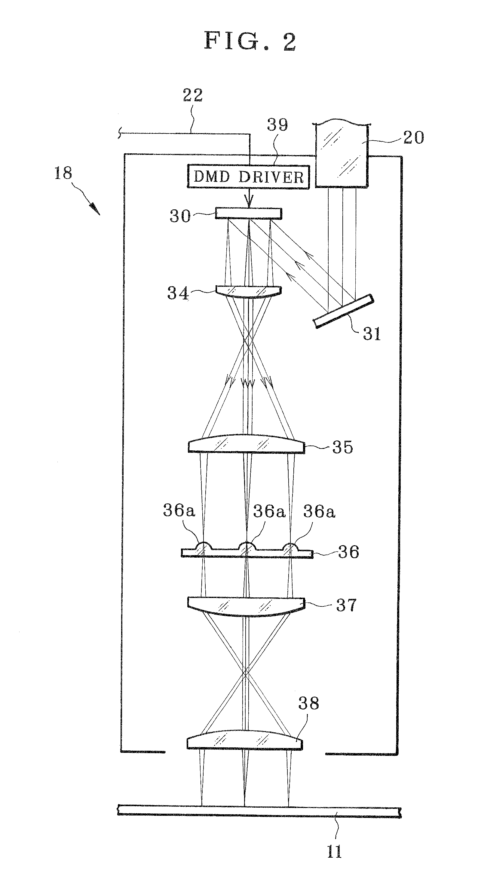
[0048]In FIG. 1, a digital exposure apparatus 10 for pattern forming includes first and second movable stages or pallets 12a and 12b. A board or substrate 11 for pattern forming is placed on and kept positioned on the first and second movable stages 12a and 12b by suction or the like. Examples of the board 11 are a printed circuit board, glass substrate for a flat panel display, and the like. A layer of photosensitive material is positioned on a surface of the board 11 by application of coating or adhesion. A base panel 14 is included in the digital exposure apparatus 10. Four legs 13 support corners of the base panel 14. Two guide rails 15 or transport path are disposed to extend in the direction Y on the base panel 14. The first and second movable stages 12a and 12b are supported by the guide rails 15 on a transport path or one dimensional orbit. A first stage moving mechanism 51a and a second stage moving mechanism 51b of FIG. 5, each of which includes a linear motor, drive respe...


PUM

PropertyMeasurementUnit
angleaaaaaaaaaa
angleaaaaaaaaaa
photosensitiveaaaaaaaaaa

Abstract

A pattern forming apparatus as exposure apparatus includes first and second movable stages for respectively supporting first and second boards placed thereon, and for transporting each board back and forth on a transport path. A pattern forming unit with DMD and laser forms a pattern on the board according to pattern data while the board moves into and out of a pattern forming region. A controller controls the pattern forming unit, and in a first period, moves a first board in a first direction on the transport path among plural boards, to form the pattern, and in a second period, moves a second board in the first direction on the transport path among the plural boards, to form the pattern. The pattern forming unit is disposed in a middle of the transport path, and is passed by the movable stages, for pattern forming selectively on the first and second boards.

Description

BACKGROUND OF THE INVENTION[0001]1. Field of the Invention[0002]The present invention relates to a pattern forming apparatus and method. More particularly, the present invention relates to a pattern forming apparatus and method in which a pattern is formed on a surface of a board, and of which a structure can be simplified at the same with high productivity.[0003]2. Description Related to the Prior Art[0004]A digital exposure apparatus is a pattern forming apparatus having a pattern forming unit. A group of spacial light modulators, such as a DMD (digital micro mirror device), are incorporated in the pattern forming unit, and are driven according to pattern data to modulate a light beam. Pattern forming is carried out on the board by exposure. The digital exposure apparatus is referred to also as a multi-beam exposure apparatus. The DMD is a mirror device including a SRAM cells or memory cells, and micro mirrors. The SRAM cells are arranged on a semiconductor substrate in a two dime...

Claims


Application Information

Patent Timeline
Patent Type & Authority Applications(United States)
IPC IPC(8): G03F7/20G03B27/42
CPCG03F7/70275G03F7/70791G03F7/70291G02B26/0833G03F7/2057G03F7/70716
Inventor FUKUI, TAKASHITERADA, KAZUHIROSHIMOYAMA, YUJISHIBATA, HIROSHIUEMURA, HIROSHI
Owner FUJIFILM CORP
Why Eureka
Try Eureka