Ophthalmic laser treatment apparatus

a laser treatment and ophthalmic technology, applied in the field of ophthalmic laser treatment apparatus, can solve the problem of not using a laser source capable of emitting a continuous wave laser beam

Active Publication Date: 2008-08-07
NIDEK CO LTD
View PDF11 Cites 10 Cited by
  • Summary
  • Abstract
  • Description
  • Claims
  • Application Information

AI Technical Summary

Benefits of technology

[0006]An object of the invention is to overcome the problems described above and to provide an ophthalmic laser treatment apparatus which allows SLT to be performed with the use of a laser source not having a Q-switch which emits a continuous wave laser beam.

Problems solved by technology

However, the conventional apparatus for SLT uses the laser source having the Q-switch in order to emit the laser beam having the extremely short pulse width of the order of nanoseconds, but does not use a laser source capable of emitting a continuous wave laser beam.
In addition, such an apparatus is dedicated only to SLT and cannot be used for other treatment.

Method used


Image

  • Ophthalmic laser treatment apparatus
  • Ophthalmic laser treatment apparatus
  • Ophthalmic laser treatment apparatus

Examples


Embodiment Construction

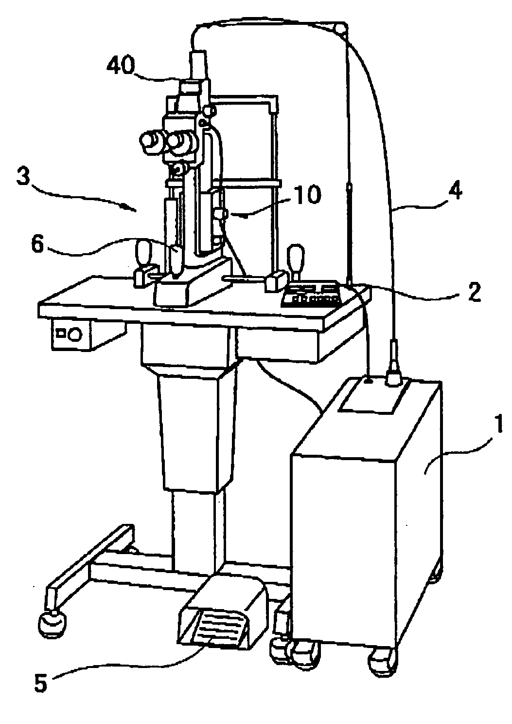
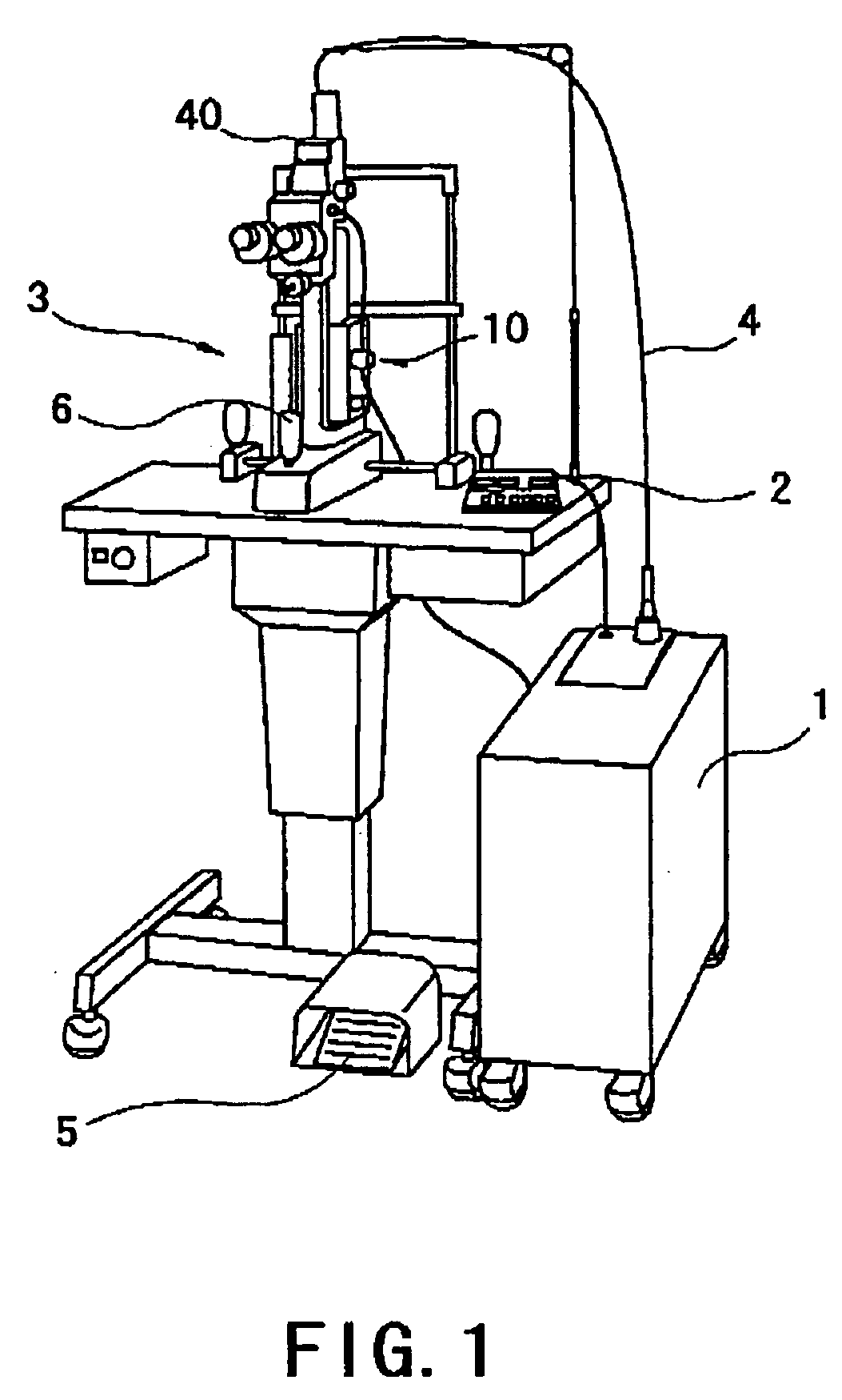
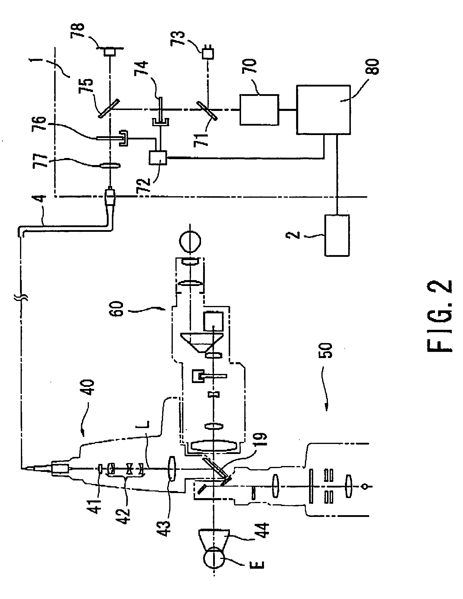
[0016]A detailed description of one preferred embodiment of an ophthalmic laser treatment apparatus embodied by the present invention is provided below with reference to the accompanying drawings. FIG. 1 is a schematic external view showing the laser treatment apparatus according to the preferred embodiment of the present invention. FIG. 2 is a schematic view showing an optical system and a control system of the laser treatment apparatus.

[0017]A main body 1 of the laser treatment apparatus incorporates a laser source 70 which emits a continuous wave visible treatment laser beam (hereinafter, referred to as the treatment beam), a laser source 78 which emits an aiming laser beam (hereinafter, referred to as the aiming beam), and other mechanisms. The laser source 70 has a semiconductor laser as an excitation light source, an Nd:YAG crystal as a laser medium, a resonator optical system such as a total reflection mirror and an output mirror, a wavelength conversion element which convert...


PUM


Abstract

An ophthalmic laser treatment apparatus, which allows SLT to be performed by a laser source not having a Q-switch which emits a continuous wave laser beam, has a laser source capable of emitting a continuous wave visible laser beam to be absorbed into pigment cells of trabecular meshwork, an irradiation optical system for directing the laser beam to a patient's eye so as to irradiate the eye with the laser beam, a device for pulsing the laser beam by controlling a driving duration of the laser source or opening and closing durations of a shutter in the irradiation optical system, a device capable of setting an irradiation duration of the laser beam within a range of 0.1 msec to 5 msec in order to perform Selective Laser Trabeculoplasty, and a device capable of setting irradiation energy density of the laser beam within a range of 1 J/cm2 to 8.5 J/cm2.

Description

BACKGROUND OF THE INVENTION[0001]1. Field of the Invention[0002]The present invention relates to an ophthalmic laser treatment apparatus for performing Selective Laser Trabeculoplasty by irradiating a patient's eye with a laser beam.[0003]2. Description of Related Art[0004]Conventionally, there is known an apparatus for performing Selective Laser Trabeculoplasty (SLT) in which an Nd:YAG laser source having a Q-switch and a wavelength conversion element is included, and reduction in intraocular pressure is induced by irradiating trabecular meshwork of a patient's eye with a visible laser beam having an extremely short pulse width of the order of nanoseconds which is generated by the Q-switch and emitted (see U.S. Pat. No. 5,549,596). Different from Argon Laser Trabeculoplasty which induces reduction in intraocular pressure by coagulating (photocoagulating) trabecular meshwork with a laser beam and constricting a part of the trabecular meshwork, SLT allows treatment by re-irradiation ...

Claims


Application Information

Patent Timeline
Patent Type & Authority Applications(United States)
IPC IPC(8): A61B18/20
CPCA61F2009/00868A61F9/008
Inventor ABE, HITOSHI
Owner NIDEK CO LTD
Why Eureka
Try Eureka