Elevator Cab Ceiling with Dissipative Ventilation Channel

Inactive Publication Date: 2008-08-14
OTIS ELEVATOR CO
View PDF16 Cites 18 Cited by
  • Summary
  • Abstract
  • Description
  • Claims
  • Application Information

AI Technical Summary

Benefits of technology

[0008]The elevator cab ceiling includes a ventilation channel and a sound absorber that improves ride quality by reducing undesirable noise transmission into an elevator cab. The various features and advantages of this inve

Problems solved by technology

By selecting a proper material for the acoustically resistive element, a maximum acoustic absorption coeff

Method used


Image

  • Elevator Cab Ceiling with Dissipative Ventilation Channel
  • Elevator Cab Ceiling with Dissipative Ventilation Channel
  • Elevator Cab Ceiling with Dissipative Ventilation Channel

Examples


Example

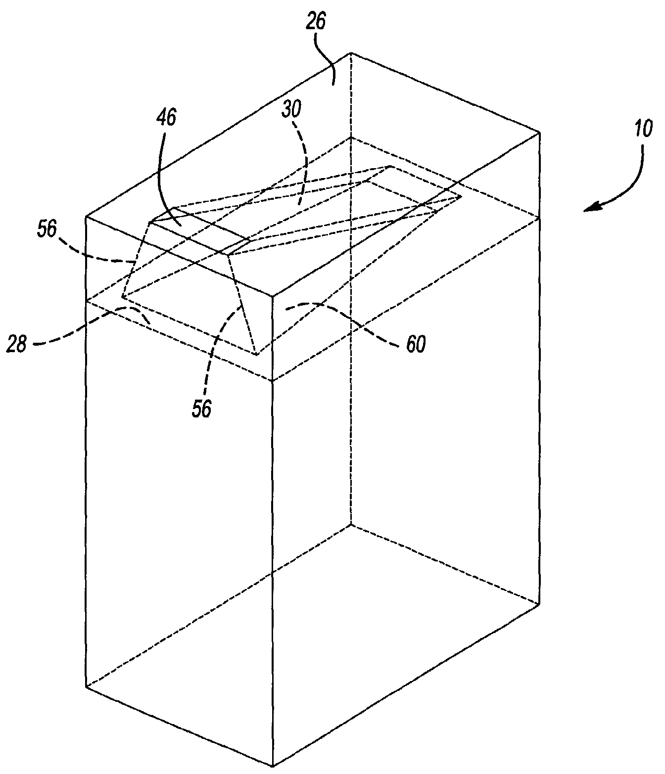
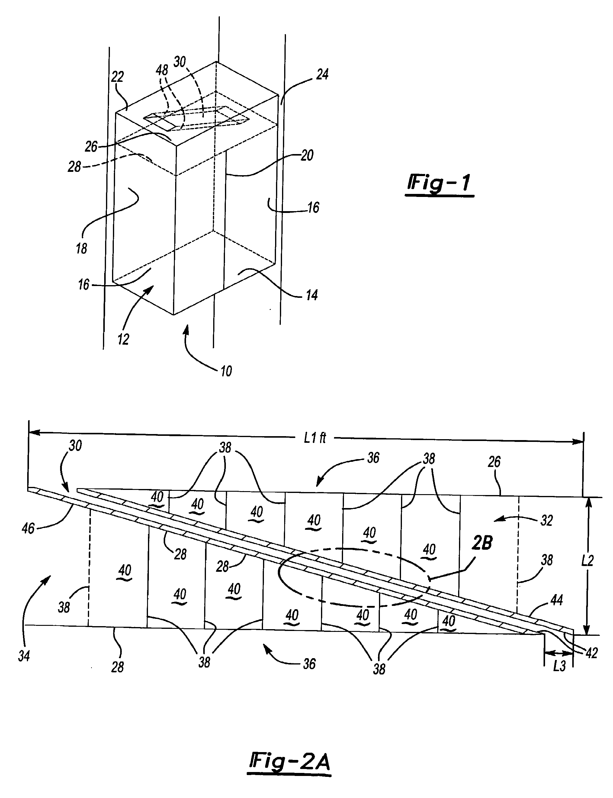
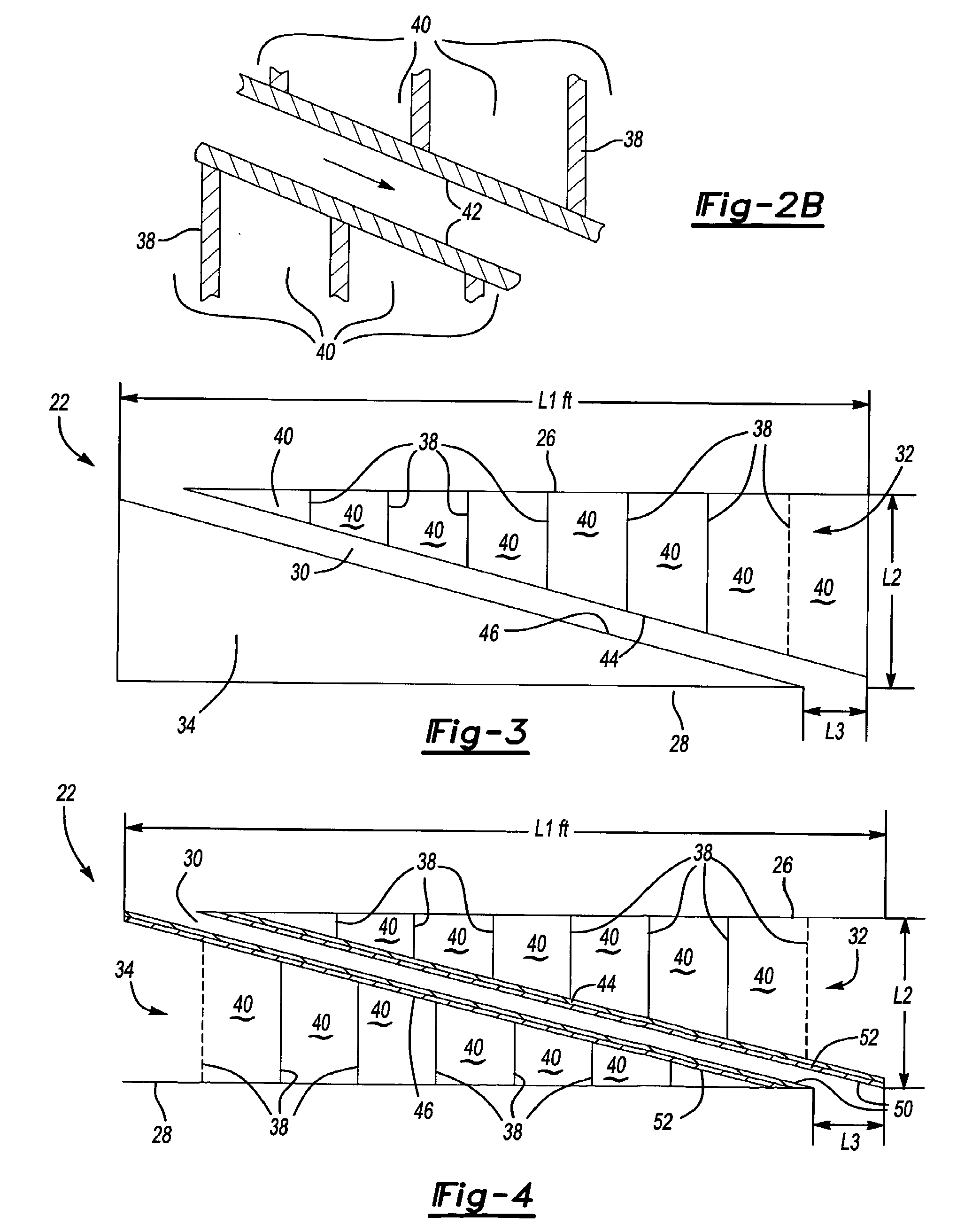
[0016]As seen in FIG. 1, an elevator cab 10 includes a passenger compartment 12 defined by a floor 14, a pair of side walls 16, a back wall 18, a pair of elevator doors 20, and a ceiling 22. An elevator machine (not shown) is used to move the elevator cab 10 within an elevator hoistway 24.

[0017]The ceiling 22 includes a first ceiling panel 26 and a second ceiling panel 28. The first and second ceiling panels 26 and 28 are spaced apart from each other and are positioned in an overlapping relationship. An air duct or ventilation channel 30 extends between the first and second ceiling panels 26 and 28. In one example, the ventilation channel 30 extends from the first ceiling panel 26 to the second ceiling panel 28 at least partially at an oblique angle relative to the first ceiling panel 26. It should be understood that while the ventilation channel 30 is shown as being generally straight, the ventilation channel 30 could be curved to accommodate lighting fixtures or other components (...


PUM

PropertyMeasurementUnit
Angleaaaaaaaaaa
Noiseaaaaaaaaaa

Abstract

An elevator cab ceiling (22) includes an upper ceiling panel (26), a lower ceiling panel (28), and a ventilation channel (30) extending between the upper ceiling panel (26) and the lower ceiling panel (28). The ventilation channel (30) extends at an oblique angle relative to the upper ceiling panel (26) and separates space between the upper (26) and lower (28) ceiling panels into an upper cavity (32) and a lower cavity (34). A plurality of partitions (36) are formed within at least one of the upper (32) or lower (34) cavities. In one example, an acoustically resistive element (42) extends at least partially along a portion of the ventilation channel (30). The plurality of partitions (36) and the acoustically resistive element (42) cooperate to reduce noise levels transmitted into an elevator cab (10) via the ventilation channel (30).

Description

FIELD OF THE INVENTION[0001]This invention generally relates to elevator systems. More particularly, this invention relates to an elevator cab ceiling having a sound absorbing ventilation channel.DESCRIPTION OF THE RELEVANT ART[0002]An elevator cab ceiling typically includes a ventilation duct or channel that allows airflow between an elevator cab and a hoistway. A ventilation fan facilitates airflow within the ventilation channel. Traditionally, the ventilation channel is formed as a vertical duct that extends straight through the ceiling. Typically, the ventilation channel extends straight down from an upper opening at a top portion of the elevator cab to a lower opening in the ceiling within the elevator cab.[0003]An elevator machine drives a rope system to move the elevator cab within a hoistway. During elevator operation, noise from the elevator machine, hoistway, rope radiation, and the ventilation fan can be easily transmitted into the elevator cab. This noise can disturb a p...

Claims


Application Information

Patent Timeline
IPC IPC(8): B66B11/02G10K11/16
CPCY10T29/49826B66B11/024
Inventor PATRICK, WILLIAM P.ZENG, QINQIAN
Owner OTIS ELEVATOR CO
Why Eureka
Try Eureka