
Fuel injection valve

a fuel injection valve and valve body technology, applied in the direction of fluid pressure injection control, fuel injection apparatus, charge feed system, etc., can solve the problems of inaccurate control of the pressure control chamber b>190/b>, and the inability of the needle b>140/b> to properly open and close the nozzle holes, etc., to achieve accurate fuel injection and stable control

Active Publication Date: 2008-08-14
DENSO CORP
View PDF6 Cites 0 Cited by
  • Summary
  • Abstract
  • Description
  • Claims
  • Application Information

AI Technical Summary

Benefits of technology

[0007]In view of the foregoing and other problems, it is an object of the present invention to produce a fuel injection valve having a nozzle cavity accommodating a needle, the needle capable of being stably controlled for producing accurate fuel injection.
[0008]According to one aspect of the present invention, a fuel injection valve comprises a housing having a tip end defining a nozzle hole. The housing further has a wall surface on an opposite side of the nozzle hole. The housing further has a fuel passage opening in the wall surface. The fuel passage communicates with the nozzle hole through a nozzle cavity. The fuel injection valve further comprises a valve element accommodated in the nozzle cavity for opening and closing the nozzle hole. The fuel injection valve further comprises a cylinder having one end substantially in contact with the wall surface. The cylinder has an inner circumferential periphery slidably accommodating one end of the valve element. The cylinder partitions the nozzle cavity substantially into a fuel accumulator chamber and a pressure control chamber. The fuel accumulator chamber is adapted to accumulating fuel supplied from the fuel passage. The pressure control chamber is adapted to accumulating fuel for manipulating the valve element. The cylinder has an outer wall defining a deflecting surface adapted to radially outwardly deflecting fuel flowing from the fuel passage.

Problems solved by technology

Consequently, pressure in the pressure control chamber 190 cannot be properly controlled.
As a result, the needle 140 cannot be accuracy controlled to properly open and close the nozzle holes 130.

Method used


Image

  • Fuel injection valve
  • Fuel injection valve
  • Fuel injection valve

Examples


first embodiment

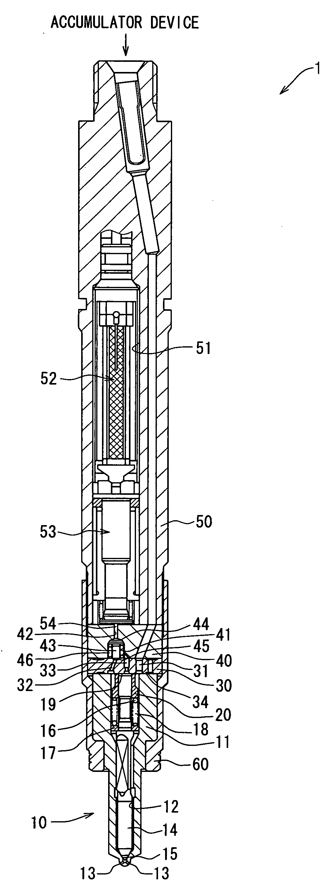
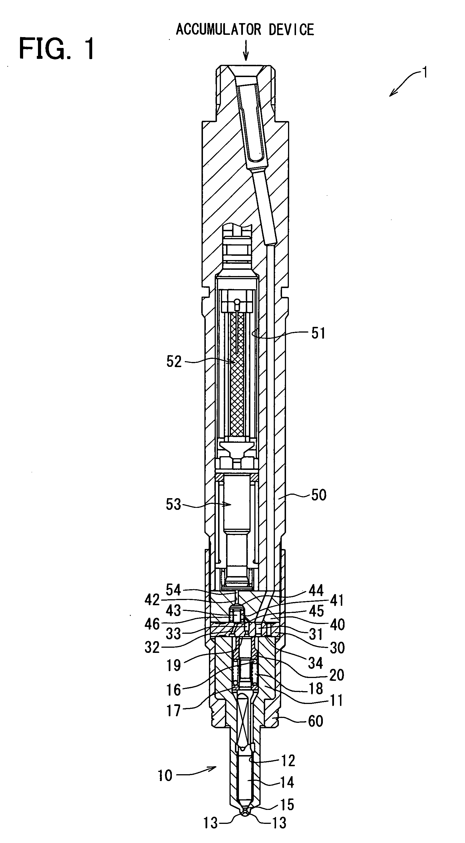
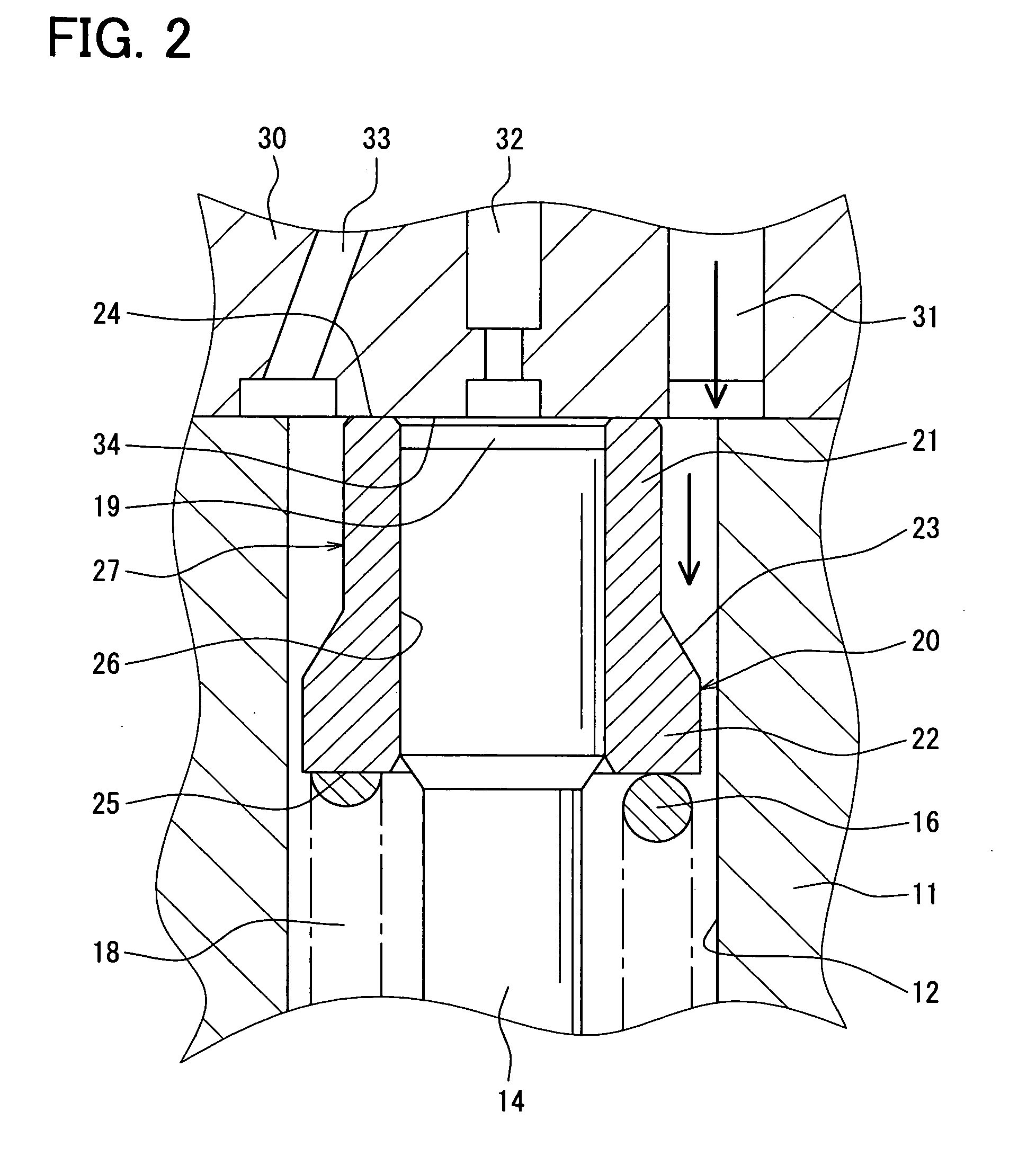
[0017]As shown in FIG. 1, the fuel injection valve 1 is used for an accumulator fuel injection device of a diesel engine, for example. The fuel injection valve 1 is supplied with high-pressure fuel from an accumulator device (common rail, not shown). The fuel injection valve 1 injects the high-pressure fuel to a combustion chamber of the engine. Fuel injection valve 1 includes an injection nozzle 10, an orifice plate 30, a valve body 40, a control valve 43, a lower body 50, a piezo actuator 52, a driving force transmission part 53, and the like. The injection nozzle 10, the orifice plate 30, the valve body 40, and the lower body 50 are stacked from the lower side in this order and screwed to each other with a retaining nut 60, thereby constructed to the fuel injection valve 1. The injection nozzle 10 includes a nozzle body 11, a needle 14, a cylinder 20, and a coil spring 16. The nozzle body 11 has a nozzle cavity 12 extending from the upper end closely to the lower end thereof. The...

second embodiment

[0055]As shown in FIG. 6, in the second embodiment, a fuel passage 31a is different from the fuel passage 31 in the first embodiment. The diameter of an open end 36a of the fuel passage 31a is equal to or less than the distance between the outer wall of the small diameter portion 21 of the cylinder 20 and the inner wall defining the nozzle cavity 12. The distance from the center axis of the nozzle cavity 12 to the inner wall defining the fuel passage 31a on the radially outer side substantially coincides with the distance from the center axis of the nozzle cavity 12 to the inner wall defining the nozzle cavity 12.

[0056]That is, the nozzle cavity 12 has an imaginary center axis at a first distance radially from a first inner wall defining the fuel passage 31a on a radially outer side. The imaginary center axis of the nozzle cavity 12 is at a second distance radially from a second inner wall defining the nozzle cavity 12. The first distance is substantially equal to the second distanc...


PUM


Abstract

A fuel injection valve includes a housing having a wall surface on an opposite side of the nozzle hole. A fuel passage opens in the wall surface, and communicates with a nozzle hole through a nozzle cavity. The nozzle cavity accommodates a valve element. A cylinder is substantially in contact with the wall surface at one end, and slidably accommodating one end of the valve element. The cylinder partitions the nozzle cavity substantially into a fuel accumulator chamber and a pressure control chamber. The fuel accumulator chamber accumulates fuel supplied from the fuel passage. The pressure control chamber accumulates fuel for manipulating the valve element. The cylinder has an outer wall defining a deflecting surface for radially outwardly deflecting fuel flowing from the fuel passage.

Description

CROSS REFERENCE TO RELATED APPLICATIONS[0001]This application is based on and incorporates herein by reference Japanese Patent Applications No. 2007-29564 filed on Feb. 8, 2007 and No. 2007-286517 filed on Nov. 2, 2007.FIELD OF THE INVENTION[0002]The present invention relates to a fuel injection valve.BACKGROUND OF THE INVENTION[0003]According to U.S. Pat. No. 6,705,551 B1 (JP-A-2003-506622), as shown in FIG. 7, a fuel injection valve 100 has a fuel accumulator chamber 180 and a pressure control chamber 190 partitioned from each other by a cylinder 200. The fuel accumulator chamber 180 has a nozzle cavity 120 accommodating a valve element (needle) 140 adapted to opening and closing nozzle holes 130. The nozzle cavity 120 accumulates high-pressure fuel to be injected through the nozzle holes 130. The pressure control chamber 190 accumulates high-pressure fuel for controlling the opening and closing of the nozzle holes 130 using the needle 140.[0004]The cylinder 200 of the fuel inject...

Claims


Application Information

Patent Timeline
Patent Type & Authority Applications(United States)
IPC IPC(8): F02M61/16
CPCF02M47/027F02M2547/001F02M61/16
Inventor KURIMOTO, NAOKITOYAO, TETSUYAMATSUMOTO, SHUICHIOOHATA, KOUICHI
Owner DENSO CORP
Learn More