Connecting Head Stucture For High-Pressure Fuel Injection Pipes

a high-pressure fuel injection and connecting head technology, which is applied in the direction of hose connection, combustion air/fuel-air treatment, machines/engines, etc., can solve the problems of cavitation erosion and other problems, and achieve the effect of increasing the width of both seat surfaces, reducing fatigue, and increasing diameter and stress concentration

Active Publication Date: 2009-06-04
USUI KOKUSAI SANGYO KAISHA LTD
View PDF61 Cites 31 Cited by
  • Summary
  • Abstract
  • Description
  • Claims
  • Application Information

AI Technical Summary

Benefits of technology

[0014]In the connecting head structure for high-pressure fuel injection pipes according to the present invention, since the inner peripheral surface of the connecting head has an outline of a section of a substantially flat face in the pipe axial direction close to the inner peripheral surface of the steel pipe, little or no pocket (annular recessed portion) generated by plastic machining exists inside the connecting head. Thus, there is no fear of generation of a crack at a trough portion of the pocket portion in molding of the head, generation of a crack by cavitation erosion by a fluid pressure in the head, and the phenomenon of tensile stress rise of the inner surface by increased diameter and stress concentration, and a possibility that the inner peripheral surface of the connecting head becomes a starting point of fatigue breakdown can be radically reduced.
[0015]Also, by increasing the vertex angle and the maximum diameter of the conical surface of the connecting head, which increases the width of the both seat surfaces at tightening, deformation of the both seat surfaces can be reduced by preventing rise of the maximum contact surface pressure, and a remaining deformation amount of the mating seat surface at releasing can be made small.
[0016]Moreover, in the connecting head structure of the present invention, when the thickness of the high-pressure fuel injection pipe is relatively small and the spherical body of the connecting head seat surface is relatively large (when the pipe inner diameter Din is 0.4D to 0.63D and the spherical radius R of the seat surface is 0.57D to 0.65D, for example), by making the inner diameter portion of the connecting head conical, a volume of a space constituting the connecting head is increased and the volume of the steel material is reduced, and by actively bringing a core metal into contact with the inner surface in molding of the head, buckling is reduced and the pocket can be made further small. Furthermore, even if the pipe inner diameter Din is in a range of 0.4D to 0.63D and the annular flange portion back face is conical, for example, the pocket can be made further small. Furthermore, even outside the range such that the pipe inner diameter is less than 0.4D or the spherical radius R is less than 0.57D, for example, by making the inner diameter portion of the connecting head conical, an effect can be obtained that the pocket can be made further small or can be eliminated.
[0017]In the present invention, a plastic deformation amount of a seal surface (seat surface) of a mating part joint portion such as a common rail is reduced by providing a soft layer on the seat surface, and high sealing performance can be obtained at repeated tightening. Moreover, since a distance from the head end to the annular flange portion is relatively reduced in the connecting head of the present invention, rigidity of the spherical seat portion is enhanced, permanent deformation such as narrowing of the head opening involved with tightening can be prevented, and seating on a pressure receiving seat surface of the mating part joint portion is stabilized. Also, fuel diffusion due to leakage or disengagement of a connection portion can be prevented against repeated pressurization of a super high-pressure fuel flow and vibration of a diesel internal-combustion engine or the like and combined with smoothing action of the fuel flow due to absence of the annular pocket, accurate fuel injection is enabled.

Problems solved by technology

However, there have been problems that cavitation erosion might occur in the vicinity of the pocket portion due to the high-pressure fluid when used, a radial crack might be generated radially in the connecting head portion from the pocket as a starting point due to fatigue breakdown, or a circumferential crack might be caused around the pocket due to the fatigue breakdown.

Method used


Image

  • Connecting Head Stucture For High-Pressure Fuel Injection Pipes
  • Connecting Head Stucture For High-Pressure Fuel Injection Pipes
  • Connecting Head Stucture For High-Pressure Fuel Injection Pipes

Examples


first embodiment

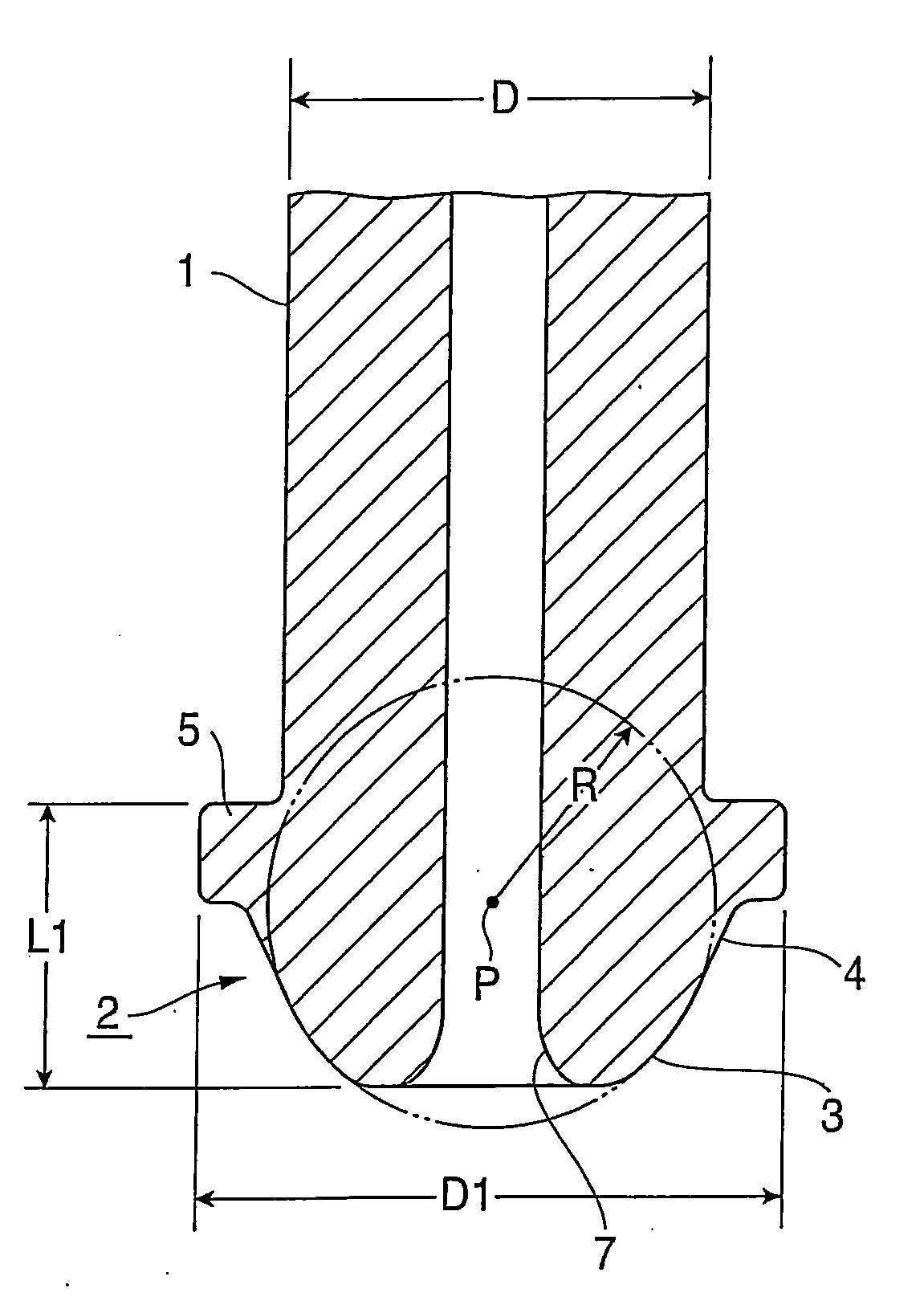
[0079]Using a thick-wall small-diameter steel pipe with the pipe diameter D of 8.0 mm, the pipe inner diameter Din of 4.0 mm and the thickness t of 2.0 mm (t / D=0.25), (material: EN E355), after the opening end of the steel pipe is chamfered, the connecting head shown in FIG. 1 is molded by the head molding method shown in FIG. 15. For the pipe diameter D and the thickness t of the thick-wall small-diameter steel pipe in this embodiment, the axial distance L1 from the connecting head end of the obtained connecting head to the annular flange portion back face, the spherical radius R of the seat surface, and the annular flange portion outer diameter D1 are L1=3.9 mm, R=4.2 mm, and D1=10.0 mm, respectively, but generation of a pocket (annular recess) is not found on the inner peripheral surface of the connecting head.

second embodiment

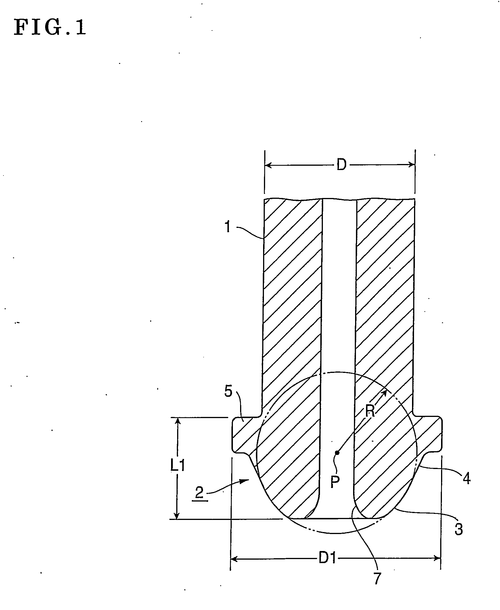
[0080]Using a thick-wall small-diameter steel pipe with the pipe diameter D of 8.0 mm, the pipe inner diameter Din of 4.0 mm and the thickness t of 2.0 mm (t / D=0.25) (material: EN E355), after the opening end of the steel pipe is chamfered, the connecting head with the sectional structure shown in FIG. 3 is molded using the punching member 11 with the root portion of the core metal 11-4 in the tapered configuration with a large diameter by the head molding method shown in FIG. 15. For the pipe diameter D and the thickness t of the thick-wall small-diameter steel pipe in this embodiment, the axial distance L1 from the connecting head end of the obtained connecting head to the annular flange portion back face, the spherical radius R of the seat surface, the annular flange portion outer diameter D1, the vertex angle θ of the conical surface and the maximum diameter D3 of the conical surface are L1=3.9 mm, R=4.2 mm, D1=10.0 mm, 0=56 degrees, and D3=8.5 mm, and the hardness of the vicini...

third embodiment

[0082]Using a thick-wall small-diameter steel pipe with the pipe diameter D of 6.0 mm, the pipe inner diameter Din of 3.0 mm and the thickness t of 1.5 mm (t / D=0.25) (material: EN E355), after the opening end of the steel pipe is chamfered, the connecting head with the conical surface shown in FIG. 12 is molded using the punching member 11 with the root portion of the core metal 11-4 in the tapered configuration with a large diameter by the head molding method shown in FIG. 15. For the pipe diameter D, the pipe inner diameter Din, and the thickness t of the thick-wall small-diameter steel pipe in this embodiment, the axial distance L1 from the connecting head end of the obtained connecting head to the annular flange portion back face, the spherical radius R of the seat surface, the annular flange portion outer diameter D1, the taper depth LT of the conical surface, and the tip-end opening diameter DT are L1=3.0 mm, R=3.75 mm, D1=8.4 mm, LT=2.8 mm, DT=4.2 mm, and generation of a pock...


PUM

PropertyMeasurementUnit
vertex angle θ1aaaaaaaaaa
vertex angle θ2aaaaaaaaaa
vertex angleaaaaaaaaaa

Abstract

A thick-wall small-diameter high-pressure fuel injection pipe has a spherical seat surface, an annular flange, and a conical surface continued from the seat surface at a connecting end of the pipe. If the pipe is configured so that t (thickness)/D (outer diameter)<0.3, then an axial distance from the connecting head end to the back face of the annular flange is 0.38D to 0.6D, a spherical radius of the seat surface is 0.45D to 0.65D, the annular flange outer diameter is 1.2D to 1.4D, and an inner peripheral surface of the head has a substantially flat cylindrical surface or a conical surface. If the pipe is configured so that t (thickness)/D (outer diameter)≧0.3, then the axial distance from the connecting head end to the back face of the annular flange is 0.38D to 0.7D.

Description

BACKGROUND OF THE INVENTION[0001]1. Field of the Invention[0002]The present invention relates to a connecting head structure for high-pressure fuel injection pipes made from thick-wall steel pipes with a relatively small diameter disposed and commonly used as a supply passage for a fuel in a diesel internal-combustion engine, for example.[0003]2. Description of the Related Art[0004]A known conventional high-pressure fuel injection pipe having this type of connecting head has, as exemplified in FIG. 17, a connecting head portion 112 of a thick-wall steel pipe 111 with a relatively small diameter in which a spherical seat surface 113, an annular flange portion 115 provided with an interval from the seat surface 113 in the shaft center direction, and an arc surface 114 continued from the seat surface 113 to the annular flange portion 115 and tapered toward the tip end (See FIG. 4 of Japanese Patent Laid-Open Print No. 2003-336560). In this type of connecting head 112, in relation to mo...

Claims


Application Information

Patent Timeline
Patent Type & Authority Applications(United States)
IPC IPC(8): F02M55/00F16L19/02
CPCF02M55/005F02M55/02F16L19/0286F02M2200/04F02M2200/8053F02M55/025F02M55/00
Inventor KATO, NOBUOHAYASHI, KOICHIUSUI, SHOICHIRO
Owner USUI KOKUSAI SANGYO KAISHA LTD
Why Eureka
Try Eureka