
Lens Module

Inactive Publication Date: 2008-08-14
JOHNSON ELECTRIC INTERNATIONAL AG
View PDF4 Cites 97 Cited by
  • Summary
  • Abstract
  • Description
  • Claims
  • Application Information

AI Technical Summary

Benefits of technology

[0006]Thus, it is an object of the present invention to provide a lens module which can be made smaller and has a fast response time.
[0020]Preferably, fingers on the lower case mate with grooves in the radially outer surface of the lens holder to guide the lens holder axially and to provide lateral support for the lens holder in the park position.

Problems solved by technology

One problem with current voice coil motor driven modules is that it is difficult to further reduce the overall size of the module, while maintaining the lens size, yet there is a strong demand to also increase the performance, in particular, the response time of the module to achieve focus from a resting position.

Method used


Image

  • Lens Module
  • Lens Module
  • Lens Module

Examples


Embodiment Construction

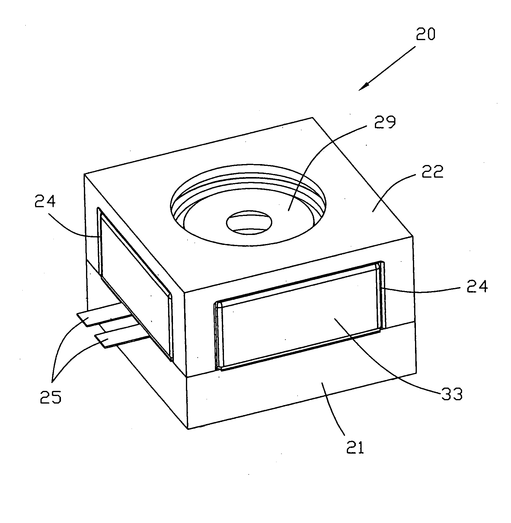
[0049]The preferred lens module 20 is shown assembled in FIG. 1 and exploded in FIG. 2. The outer appearance of the module 20 is like a squat square box measuring 10 by 10 by 5.2 mm. The module 20 has a two part casing with a lower case 21 and an upper case 22. The upper case 22 has a central hole 23 through which light from an image to be captured can pass. Additional openings 24 are formed in each side, formed by cutouts in the joining edges of the upper and lower cases. Through one of the side openings, two terminals 25 protrude for connecting the module 20 to a source of power.

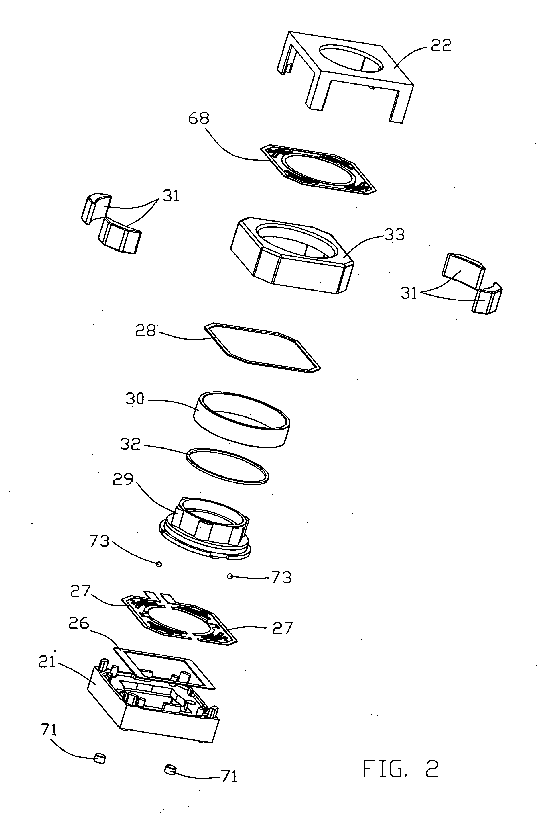
[0050]Referring to the exploded view of FIG. 2, the components of the module 20 will be named starting from the bottom. At the bottom is the lower case 21. Fixed to the floor of the lower case 21 is a lower cushion 26. Fitted or placed into the lower case are two lower springs 27. An insulating member 28 is placed on top of an outer edge of the springs 27. A lens holder 29 is supported by the inner edge of...


PUM


Abstract

A voice coil motor lens module has a lens holder adapted to carry a lens or lens assembly. The lens holder supports a coil which interacts with a permanent magnet field generated by one or more permanent magnets supported by a magnet yoke. The maximum axial movement of the lens holder is limited by the magnet yoke.

Description

CROSS-REFERENCE TO RELATED APPLICATIONS[0001]This non-provisional patent application claims priority under 35 U.S.C. § 119(a) from Patent Application No. 0702835.0 filed in Great Britain on 14 Feb. 2007.BACKGROUND OF THE INVENTION[0002]Lens modules, especially autofocus lens modules, have a lens holder to which is mounted a single lens or lens assembly, simply referred to herein as a lens, for focussing an image onto an image plane. In use, the image plane would be an image sensor such as a CMOS or CCD device but in practice, the lens module is produced bare, meaning without the lens and without the image sensor which are fitted by the camera module maker. The lens module has a lens holder which is arranged to be driven by an actuator along a short straight path. Known actuators include DC motors, stepping motors, voice coil motors, ultrasonic motors and electrostrictive actuators including piezoelectric actuators.[0003]There is a strong demand for small lens modules as small camera...

Claims


Application Information

Patent Timeline
IPC IPC(8): H04N5/228
CPCG02B7/02G02B7/08H04N5/2257G03B3/10H04N5/2254G02B13/001H04N23/57H04N23/55
Inventor NAGASAKI, YASUMASA
Owner JOHNSON ELECTRIC INTERNATIONAL AG
Features
  • Generate Ideas
  • Intellectual Property
  • Life Sciences
  • Materials
  • Tech Scout
  • Unparalleled Data Quality
  • Higher Quality Content
  • 60% Fewer Hallucinations
Learn More