Surface illumination apparatus and liquid crystal display

a technology of surface illumination and liquid crystal display, which is applied in the direction of lighting and heating apparatus, planar/plate-like light guides, instruments, etc., can solve the problems of affecting the use efficiency of the beam of light emitted from the backlight unit, power consumption increases, grave problems to be solved, etc., and achieves the effect of preserving the polarization of the laser beam and efficient laser beam us

Inactive Publication Date: 2008-08-14
PANASONIC CORP
View PDF11 Cites 37 Cited by
  • Summary
  • Abstract
  • Description
  • Claims
  • Application Information

AI Technical Summary

Benefits of technology

[0019]It is an object of the present invention to provide a surface illumination apparatus which is capable of preserving the polarization of a laser beam and using the laser beam more efficiently, and a liquid crystal display provided with this.
[0021]According to the surface illumination apparatus according to the present invention, a laser beam is incident on a liquid-crystal display panel with this laser beam's polarization preserved, so that the laser beam can be more efficiently used. This offers a great advantage in that a liquid crystal display provided with this surface illumination apparatus as a backlight unit is capable of realizing a high intensity and a low-level power consumption.

Problems solved by technology

At the same time, however, its power consumption increases as its size is larger, and thus, the necessity arises for the development of an art of lessening the power consumption.
These are grave problems to be solved.
This greatly affects the usage efficiency of a beam of light emitted from the backlight unit.
According to this configuration, however, because the reflection mirror is used, in the case where it is applied to a large-area liquid-crystal display panel, there is a disadvantage in that the surface illumination apparatus becomes thicker.
Hence, a disadvantage arises in that the cost of producing the light guide plate increases.
This raises a disadvantage in that the production of the light guide plate including the half mirrors becomes complicated to increase its cost.
Hence, they are still insufficient in performance and costs.

Method used


Image

  • Surface illumination apparatus and liquid crystal display
  • Surface illumination apparatus and liquid crystal display
  • Surface illumination apparatus and liquid crystal display

Examples


first embodiment

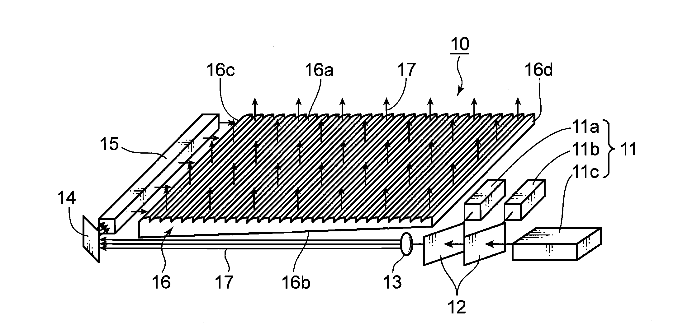
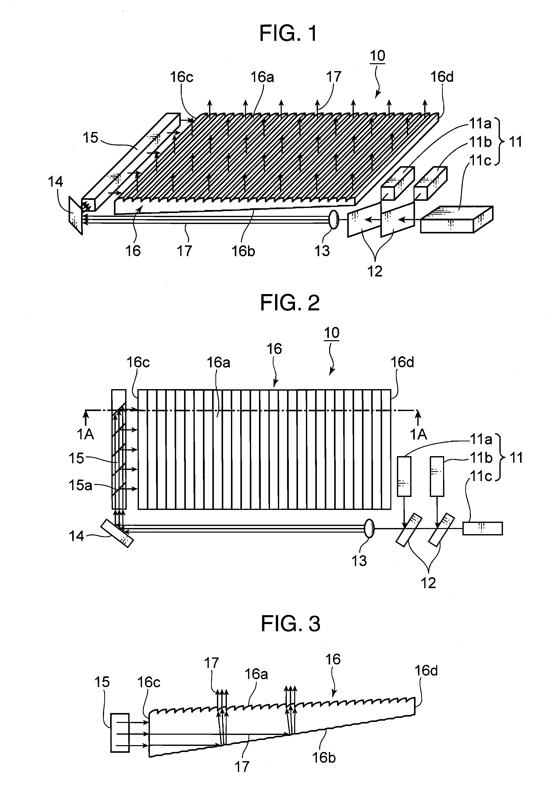
[0047]FIG. 1 is a schematic perspective view of a surface illumination apparatus 10 according to a first embodiment of the present invention, showing its configuration. FIG. 2 is a plan view of the surface illumination apparatus 10, seen from the side of one main-surface portion 16a of a light guide plate 16 shown in FIG. 1. FIG. 3 is a schematic sectional view of the surface illumination apparatus 10, cut off along a 1A-1A line shown in FIG. 2. In FIG. 1 to FIG. 3, each member is arranged apart from each other for the purpose of helping understand their configurations. However, in the actual configurations, each member is disposed on a base plate (not shown) or the like, and all the members are united and fixed.

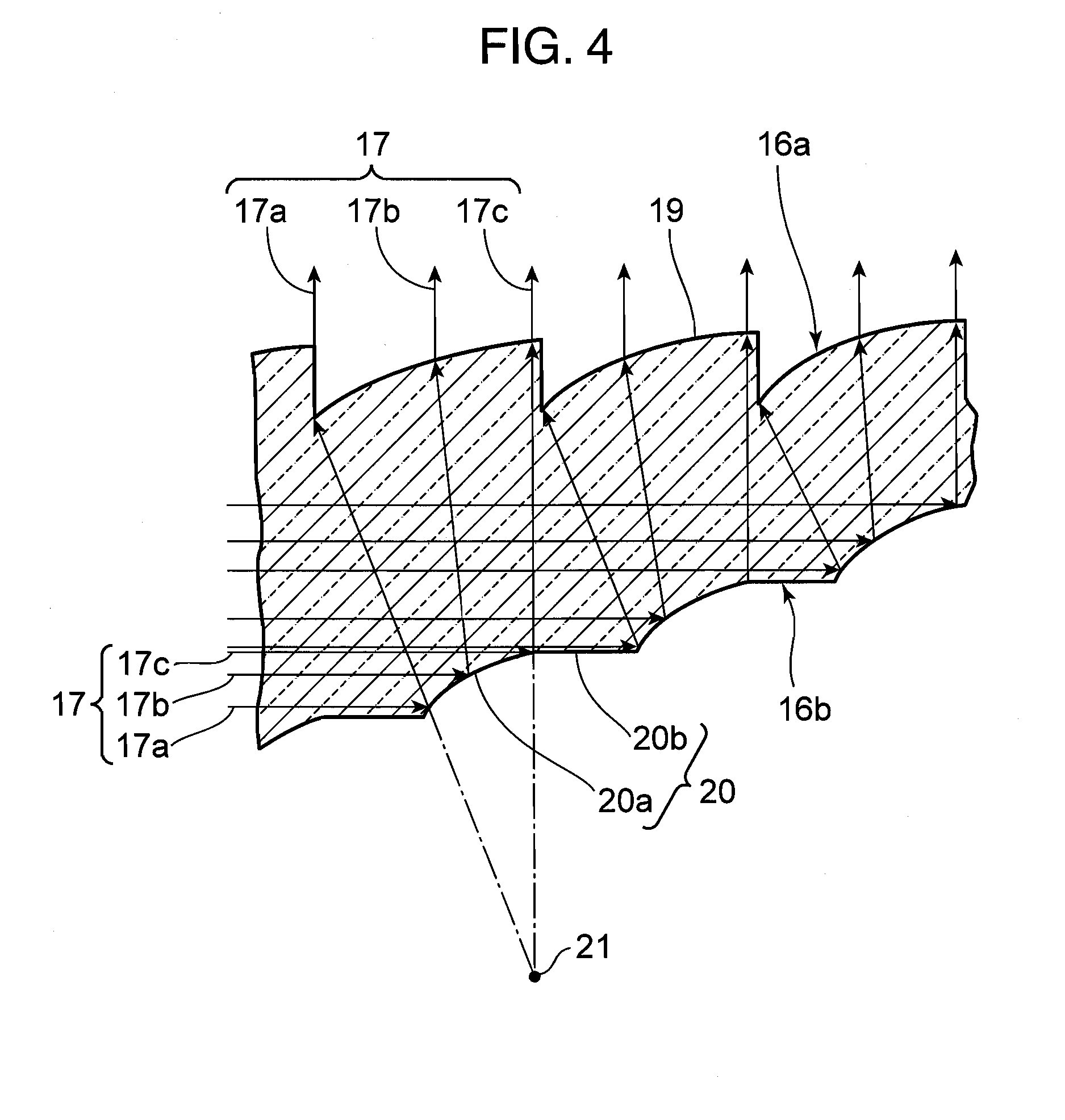
[0048]FIG. 4 is an enlarged sectional view of the board-shaped light guide plate 16, showing illustratively that a laser beam 17 incident from an end-surface light-guide plate 15 is reflected by the other main-surface portion 16b inside of the light guide plate 16 and is emi...

second embodiment

[0073]FIG. 9 is a schematic perspective view of a surface illumination apparatus 40 according to a second embodiment of the present invention, showing its configuration. FIG. 10 is a plan view of the surface illumination apparatus 40, seen from the side of a prism sheet 45 disposed over a light guide plate 42 shown in FIG. 9. FIG. 11 is a schematic sectional view of the surface illumination apparatus 40, cut off along a 5A-5A line shown in FIG. 10. In FIG. 9 to FIG. 11, each member is arranged apart from each other for the purpose of helping understand their configurations. However, in the actual configurations, each member is disposed on a base plate (not shown) or the like, and all the members are united and fixed.

[0074]FIG. 12 is a sectional view of the light guide plate, showing illustratively that the laser beam 17 incident from an end-surface light-guide plate 41 is diffracted in a main-surface portion 42b on the other side and a main-surface portion 42a on the one side, respe...

third embodiment

[0087]FIG. 14 is a plan view of a liquid crystal display 70 provided with a surface illumination apparatus 60 according to a third embodiment of the present invention, seen from the side of the surface illumination apparatus 60, showing its configuration. FIG. 15 is a schematic sectional view of the liquid crystal display 70, cut off along a 7A-7A line shown in FIG. 14. FIG. 16 is a sectional view of the surface illumination apparatus 60 used as a backlight unit for the liquid crystal display 70 shown in FIG. 14, illustrating the configuration of its main part. FIG. 17 is a sectional view of a light guide plate 66 shown in FIG. 16, illustrating the optical path of a laser beam. Hereinafter, this surface illumination apparatus 60 will be described as a backlight unit 60.

[0088]In the backlight unit 60 used in the liquid crystal display 70 according to this embodiment, a polygon mirror 62 is used as an optical system which allows a substantially parallel beam to be incident on an end-s...


PUM

PropertyMeasurementUnit
transmission-axis angleaaaaaaaaaa
wavelengthsaaaaaaaaaa

Abstract

A surface illumination apparatus is provided which includes a laser light source and a light guide plate upon which a laser beam emitted from the laser light source is incident through an end-surface portion and from which the laser beam is emitted through a main-surface portion on one side thereof. The laser beam is incident through an end-surface portion at an inclination angle to a main-surface portion on the other side which faces the one main-surface portion of the light guide plate, undergoes a change in the optical-path direction thereof by the other main-surface portion, is incident on the one main-surface portion and is emitted as a substantially parallel beam from the one main-surface portion.

Description

BACKGROUND OF THE INVENTION[0001]1. Field of the Invention[0002]The present invention relates to a surface illumination apparatus in which a laser light source is used as a source for light emission, and a liquid crystal display provided with this surface illumination apparatus.[0003]2. Description of the Background Art[0004]A liquid crystal display displays an image by controlling the transmission quantity of a beam of light projected from its rear surface, using an electro-optical effect by the orientation of liquid-crystal molecules. This method is employed, and thus in general, a backlight unit is needed which is formed by a cold-cathode fluorescent tube and the like. In such a liquid crystal display, in recent years, its screen size has become increasingly large, and even a 50-inch size display for television has been put to practical use. At the same time, however, its power consumption increases as its size is larger, and thus, the necessity arises for the development of an a...

Claims


Application Information

Patent Timeline
Patent Type & Authority Applications(United States)
IPC IPC(8): G02F1/1335G02B27/00
CPCG02B6/0016G02B6/0028G02B6/0031G02F2001/133622G02F1/133621G02F2001/133607G02B6/0046G02F1/133607G02F1/133622
Inventor ITOH, TATSUONAGATA, TAKAYUKISHIKII, SHINICHIMIZUSHIMA, TETSUROYAMAMOTO, KAZUHISAKADOWAKI, SHINICHI
Owner PANASONIC CORP
Why Eureka
Try Eureka