
Eye Movement Sensor Device

a sensor device and eye movement technology, applied in the field of eye movement sensor devices, can solve the problems of inability to achieve precise eye examination, lack of precision in measuring ocular parameters, excessive subjective interpretation of the results obtained with most existing diagnosis systems, etc., to achieve convenient and short examination, optimize diagnosis, and improve diagnostic accuracy

Inactive Publication Date: 2008-08-14
HOSPITAL SANT JOAN DE DEU
View PDF8 Cites 8 Cited by
  • Summary
  • Abstract
  • Description
  • Claims
  • Application Information

AI Technical Summary

Benefits of technology

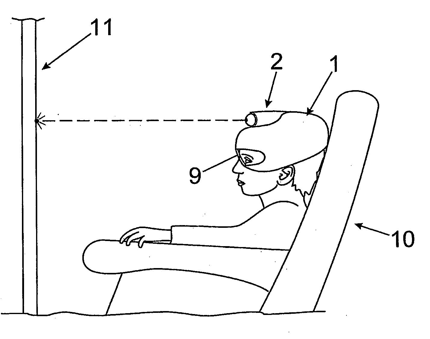
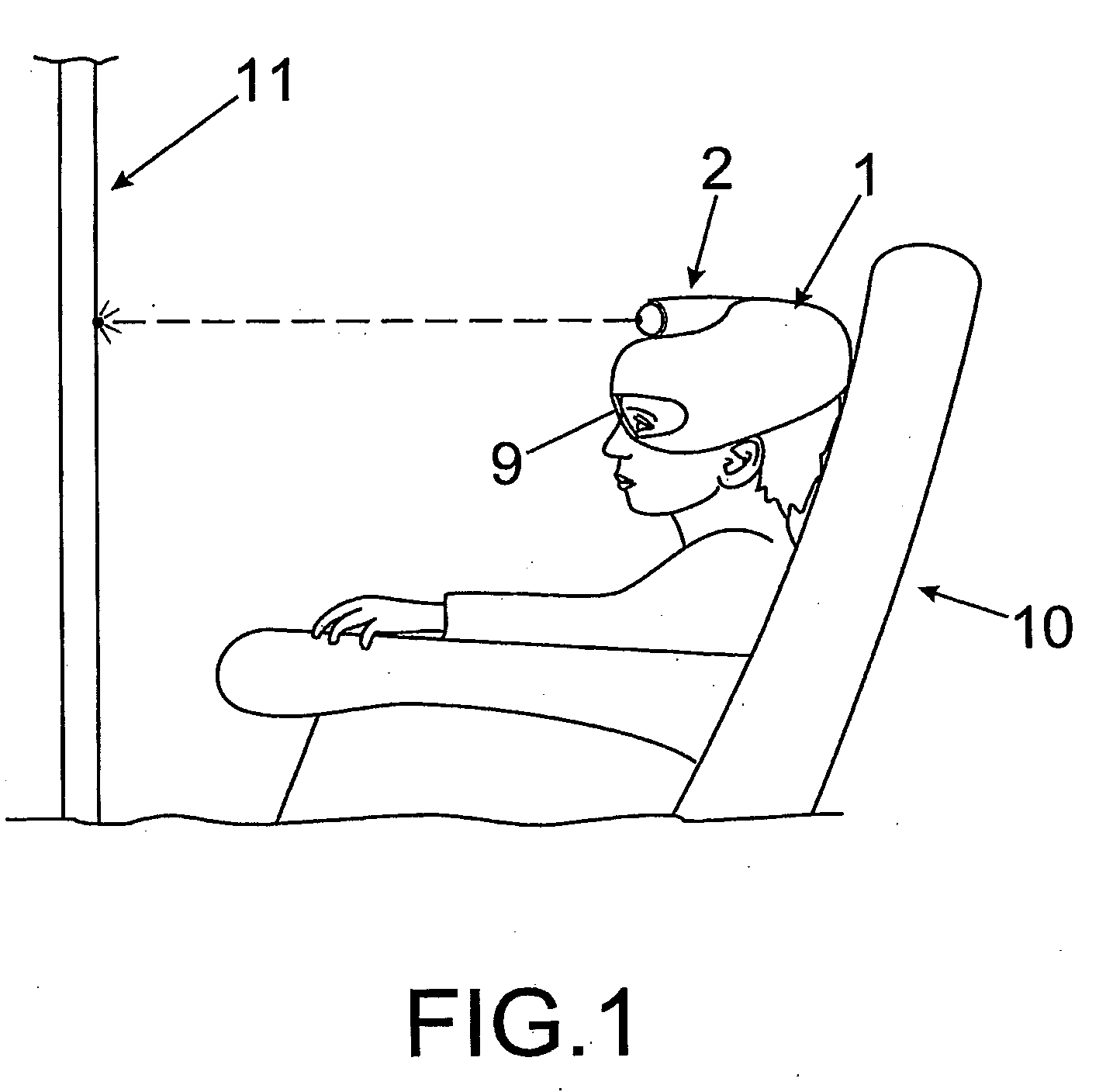
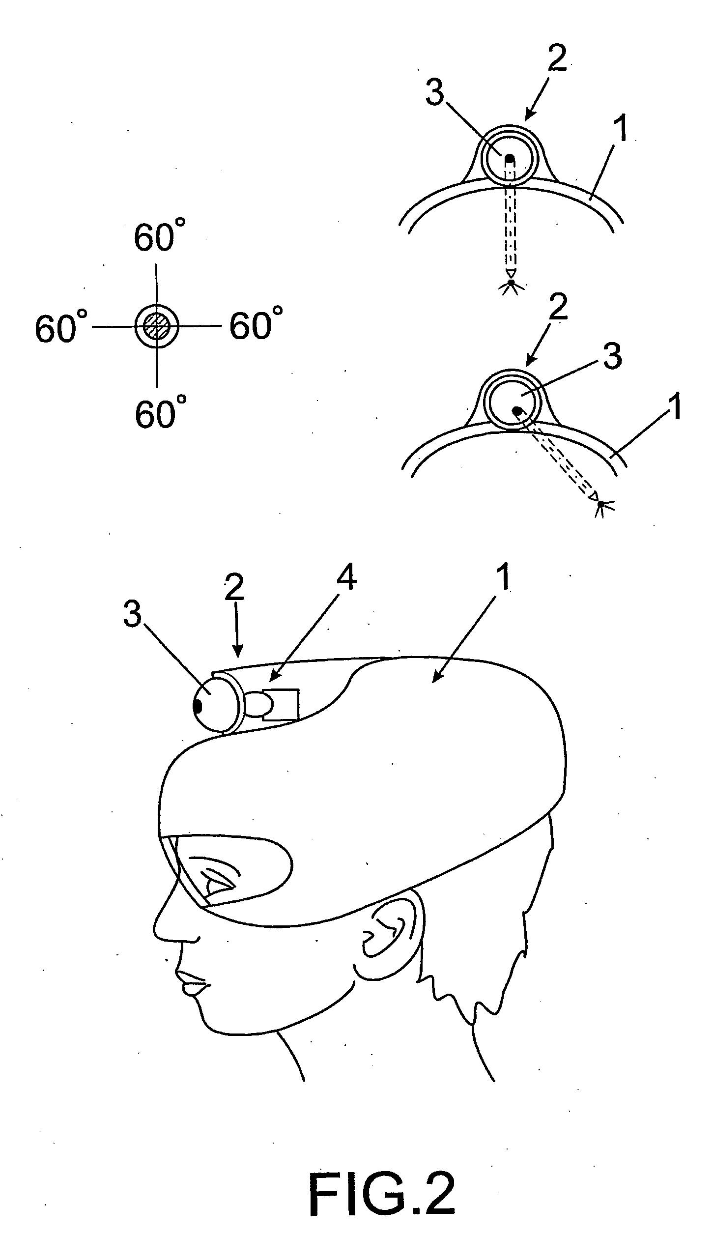
[0002]In particular, the eye movement sensor recommended comprises a helmet, applicable to both adult and children patients, which incorporates means of recording the eyes, preferably a video camera for both eyes or one for each eye, which record them in images viewed from an angle which permits capturing all their movements, which is the angle of the gaze in maximum infraduction, i.e. downward. Additionally, the helmet has a light projector which emits light spots towards a screen, which the patient is made to look at to undergo a very precise eye examination of said anomalies and optimize the diagnosis.
[0003]The object of the invention is for the patient to be able to freely move his / her head when looking at the visual tests that are normally undergone during an ophthalmologic examination, permitting a more pleasant and shorter examination, whose results are not affected by said voluntary or involuntary head movements.

Problems solved by technology

To date, a multitude of systems are known which permit determining and measuring possible ocular mobility alterations, but they all have one or several of the following problemsActive collaboration is required from the patient, which is difficult to achieve for children under the age of 6 and especially in mentally handicapped patients.The lack of precision in measuring the ocular parameters leads to the excessively subjective interpretation of the results obtained with most of the existing diagnosis systems.The strabismus detecting means known do not permit measuring deviation of the eyes at all points in the field of ocular motility of a person.
Furthermore, this method and the apparatus that executes it are based on the use of a pair of video cameras disposed frontally, in the visual axis of each eye respectively, but their position does not permit recording their entire visual field, and, in particular, prevents recording a downward gaze, since the upper lid covers the eye.
Another deficiency is that the video cameras are fixed only recording the eyes, but means for capturing movements of the head are not provided, which means the ocular motility detected with this method and apparatus is not correct if the patient, as is typical in children or the mentally handicapped, moves his / her head.
Evidently, its seems very improbable that a young person or people with mental problems would tolerate the rigid fixing of his / her head, which in any case is uncomfortable even simply using velcro tapes.
Children or even adults with any mental or physical disorders which causes chaotic movements of the head may cause too large movements of their head position, it being practically impossible to make reliable calculations of the eye movements, with respect to the point at which the gaze is directed, as it is easily possible to go outside the capturing area marked by the infrared detecting means.

Method used


Image

  • Eye Movement Sensor Device
  • Eye Movement Sensor Device
  • Eye Movement Sensor Device

Examples


Embodiment Construction

[0028]The present invention resolves, among others, the aforementioned problems, in a fully satisfactorily manner in each and every one of the different aspects commented, offering interesting advantages compared with the references.

[0029]In particular, the invention described is devised to capture eye movements, in view of its application in the detection of anomalies derived from strabismus or other diseases of the eyes and eyelids, in all types of patients, from adults in full possession of their mental and physical faculties to children under the age of six who do not provide sufficient collaboration in an ophthalmologic examination.

[0030]The eye movement sensor which is recommended comprises a helmet, in short a device designed ergonomically for the head, which incorporates means of recording of the eyes, which basically consists of at least one camera, preferably a video, to record images of each one of the eyes.

[0031]In this way, since the means of capturing eye movements, i....


PUM


Abstract

The eye movement sensor comprises a helmet (1) adjustable to the head of a patient who is undergoing an ophthalmologic examination, in a unit with seat (10) and projection screen (11) of light spots in front, the same helmet (1) incorporating a front light projector (2) which emits a light spot towards the screen (11), as well as means of image recording of each one of the eyes, which records their movements captured from an angle which permits viewing the eye in all its positions. Said means of recording preferably consists of a video camera (6) disposed below the projector (2) of the helmet (1), focussing a pair of mirrors (7), incorporated on different sides of the lower part of the helmet (1) downward, under each eye respectively, to capture the specular reflection of its movements; or instead, two cameras (5) under each eye.

Description

OBJECT OF THE INVENTION[0001]The present invention is applied to the field of ophthalmology, in particular for the detection, monitoring and optimization of the further treatment of pathologies related to certain ocular motility anomalies, such as those caused by facial paralysis, strabismus (eye deviation), blepharospasm (spastic closure of the eyes), nystagmus (accelerated eye vibration), ptosis (drooping upper eyelid), as well as the examination of eye prosthesis, etc.[0002]In particular, the eye movement sensor recommended comprises a helmet, applicable to both adult and children patients, which incorporates means of recording the eyes, preferably a video camera for both eyes or one for each eye, which record them in images viewed from an angle which permits capturing all their movements, which is the angle of the gaze in maximum infraduction, i.e. downward. Additionally, the helmet has a light projector which emits light spots towards a screen, which the patient is made to look...

Claims


Application Information

Patent Timeline
IPC IPC(8): A61B3/10
CPCA61B3/113G02B27/0172
Inventor PRAT BARTOMEU, JOAN
Owner HOSPITAL SANT JOAN DE DEU
Learn More