Test method and apparatus for tunneling magnetoresistive element

a tunneling magnetoresistive and test method technology, applied in the field of reproduction elements or read devices, can solve the problems of deteriorating reproduction output or sensitivity, lowering the sensitivity of tmr film, and lowering the resistance of tmr

Inactive Publication Date: 2008-08-14
FUJITSU LTD
View PDF3 Cites 2 Cited by
  • Summary
  • Abstract
  • Description
  • Claims
  • Application Information

AI Technical Summary

Benefits of technology

[0007]The present invention is directed to a test method and apparatus that can effectively determine whether a TMR element is defective or non-defective.

Problems solved by technology

However, any pinholes in the insulation film and any shortcircuits around the insulation film would lower the resistance of the TMR head, and deteriorate the reproduction output or the sensitivity.
However, when the shortcircuit resistance is low, the sensitivity of the TMR film lowers.
However, the conventional method cannot effectively determine whether a TMR element having a shortcircuit is defective or non-defective.
Firstly, since resistance values of TMR films scatter due to the process, the method that utilizes the resistance value cannot precisely determine whether the head is defective or non-defective based on the shortcircuit.
Secondly, the method that utilizes the resistance changing rate can determine the filming quality based on a presence of a pinhole in the TMR film, but cannot determine whether the head is defective or non-defective based on the shortcircuit.

Method used


Image

  • Test method and apparatus for tunneling magnetoresistive element
  • Test method and apparatus for tunneling magnetoresistive element
  • Test method and apparatus for tunneling magnetoresistive element

Examples


Embodiment Construction

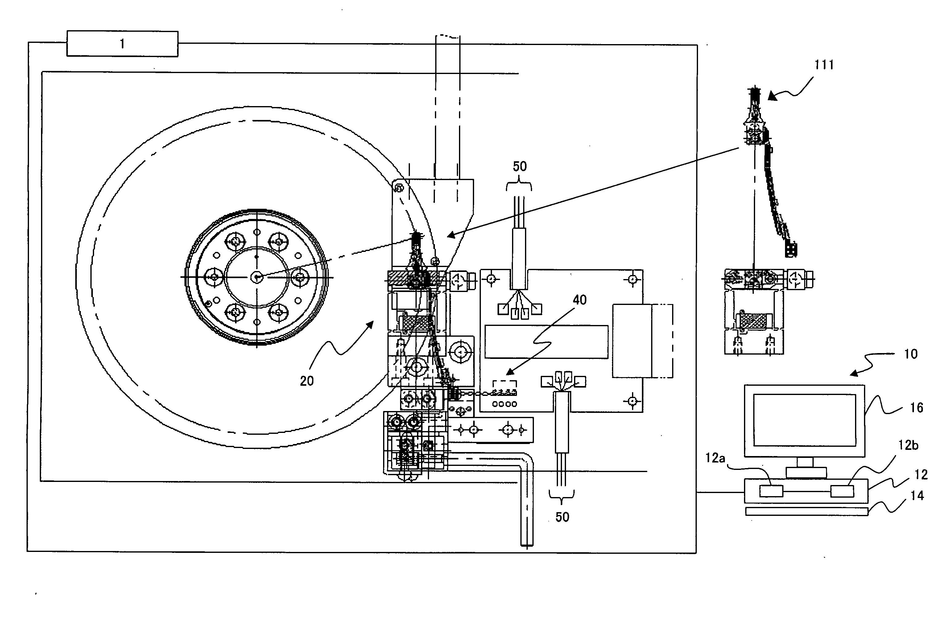
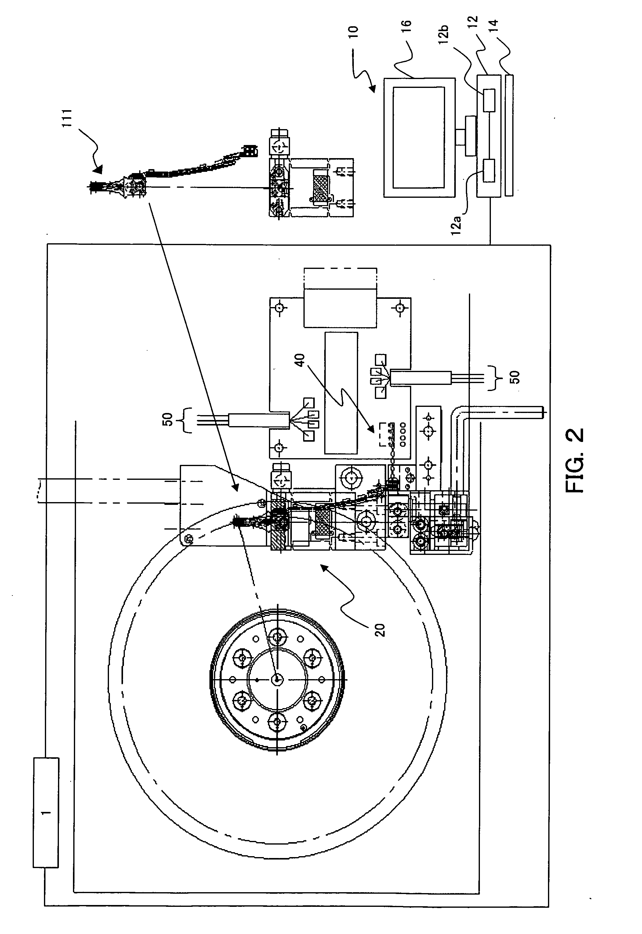
[0019]Referring now to FIG. 2, a description will be given of a test apparatus 1 for a magnetic head device for use with a HDD (storage) 100, which will be described later. The test apparatus 1 includes a personal computer (“PC”) 10, a mount member 20 to be mounted with a head gimbal assembly (“HGA”) 111 to be tested, a detector 40, and a current supply unit 50. The HGA 111 is a suspension assembly mounted with a slider, and can be referred to as a head suspension assembly.

[0020]The test apparatus 1 is a test apparatus that determines whether a HGA 111 is a defective article or a non-defective article, before the HGA 111 is mounted onto the HDD 100. As described later, the HGA 111 includes a magnetic head part 120, and the magnetic head part 120 includes a recording element (inductive head device 130) used to write information in a disc 104, which will be described later, and a reproduction element (TMR head device 140) used to read the information from the disc 104. The test appara...


PUM

PropertyMeasurementUnit
currentaaaaaaaaaa
tunneling magnetoresistive effectaaaaaaaaaa
resistanceaaaaaaaaaa

Abstract

A reproduction-element test method for a reproduction element that utilizes a tunneling magnetoresistive effect includes a measurement step for measuring first and second resistance values for different currents, a comparison step for comparing a resistance value differential curve that is calculated from a theoretical equation between tunneling magnetoresistiance and a voltage of the reproduction element of a non-defective article having the same design, with a resistance changing rate calculated from the first and second resistance values measured by the measurement step; and a determination step for determining whether the reproduction element is defective or non-defective based on a comparison between the resistance value differential curve and the resistance changing rate.

Description

[0001]This application claims the right of a foreign priority based on Japanese Patent Application No. 2007-028686, filed on Feb. 8, 2007, which is hereby incorporated by reference herein in its entirety as if fully set forth herein.BACKGROUND OF THE INVENTION[0002]The present invention relates generally to a test method for a reproduction element or read device, and more particularly to a test method for a tunneling magnetoresistive (“TMR”) element. The present invention is suitable, for example, for a test method of a TMR (head) element used for a hard disc drive (“HDD”).[0003]Along with the Internet etc., a HDD that stably reproduces a large amount of information has been increasingly demanded. As the disc's surface recording density becomes higher in order to meet the demand for a large capacity, a signal magnetic field becomes weaker. A smaller and more highly sensitive reproduction element is necessary to read this weak signal magnetic field.[0004]A known candidate of this rep...

Claims


Application Information

Patent Timeline
Patent Type & Authority Applications(United States)
IPC IPC(8): G11B27/36
CPCB82Y25/00G01R33/093G11B5/455H01F10/3254G11B27/36G11B2220/2516G11B5/4555G11B5/39H01L27/105H10N50/01H10B99/00
Inventor MATSUBARA, MASATO
Owner FUJITSU LTD
Why Eureka
Try Eureka