Phasing plug for acoustic compression drivers

Inactive Publication Date: 2008-08-14
LEWALLEN VERNON
View PDF12 Cites 25 Cited by
  • Summary
  • Abstract
  • Description
  • Claims
  • Application Information

AI Technical Summary

Benefits of technology

[0018]The phasing plug of the present invention provides numerous advantages over current phasing plugs and has particular advantages when used with a compression driver. The sound wave absorbing portion or region of the phasing plug absorbs phase distorted sound waves and at the same time, the phasing plug transmits coherent sound waves, such as coherent low and midrange sound waves and sound waves generated at the outer edges or exterior portions of the diaphragm. As a result the phasing plug transmits sound with increased clarity over the high-frequency range, while at the same time, maintaining audible definition over the high to midrange sound wave spectrum.
[0019]The improved phasing plug reduces the need for electronic signal processing or equalization of the input signals to the compression driver and thus avoids over-heating of the voice coil resulting in energy conservation and increased com

Problems solved by technology

These prior attempts have not produced satisfactory results in transforming the sound waves generated by the diaphragm without high frequency interference or distortion.
Compression drivers comprising a traditional diaphragm coupled with known phasing plugs thus suffer from phase distortions that distort high frequency sound waves.
The high fidelity sounds are suppressed and high quality reproduction of voice and

Method used


Image

  • Phasing plug for acoustic compression drivers
  • Phasing plug for acoustic compression drivers
  • Phasing plug for acoustic compression drivers

Examples


Example

[0037]In the following description, numerous specific details are set forth in order to provide a more thorough description of the present invention. It will be apparent, however, to one skilled in the art, that the present invention may be practiced without these specific details. In other instances, well-known features have not been described in detail so as not to obscure the invention.

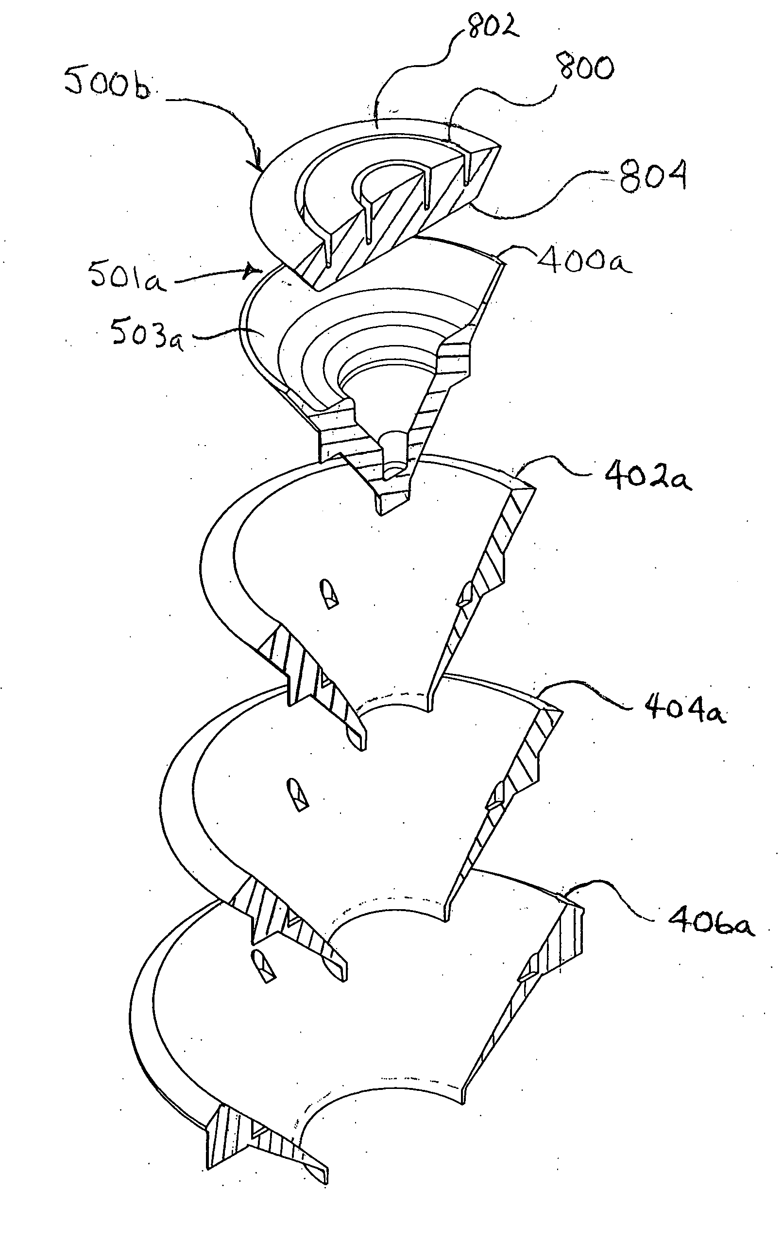
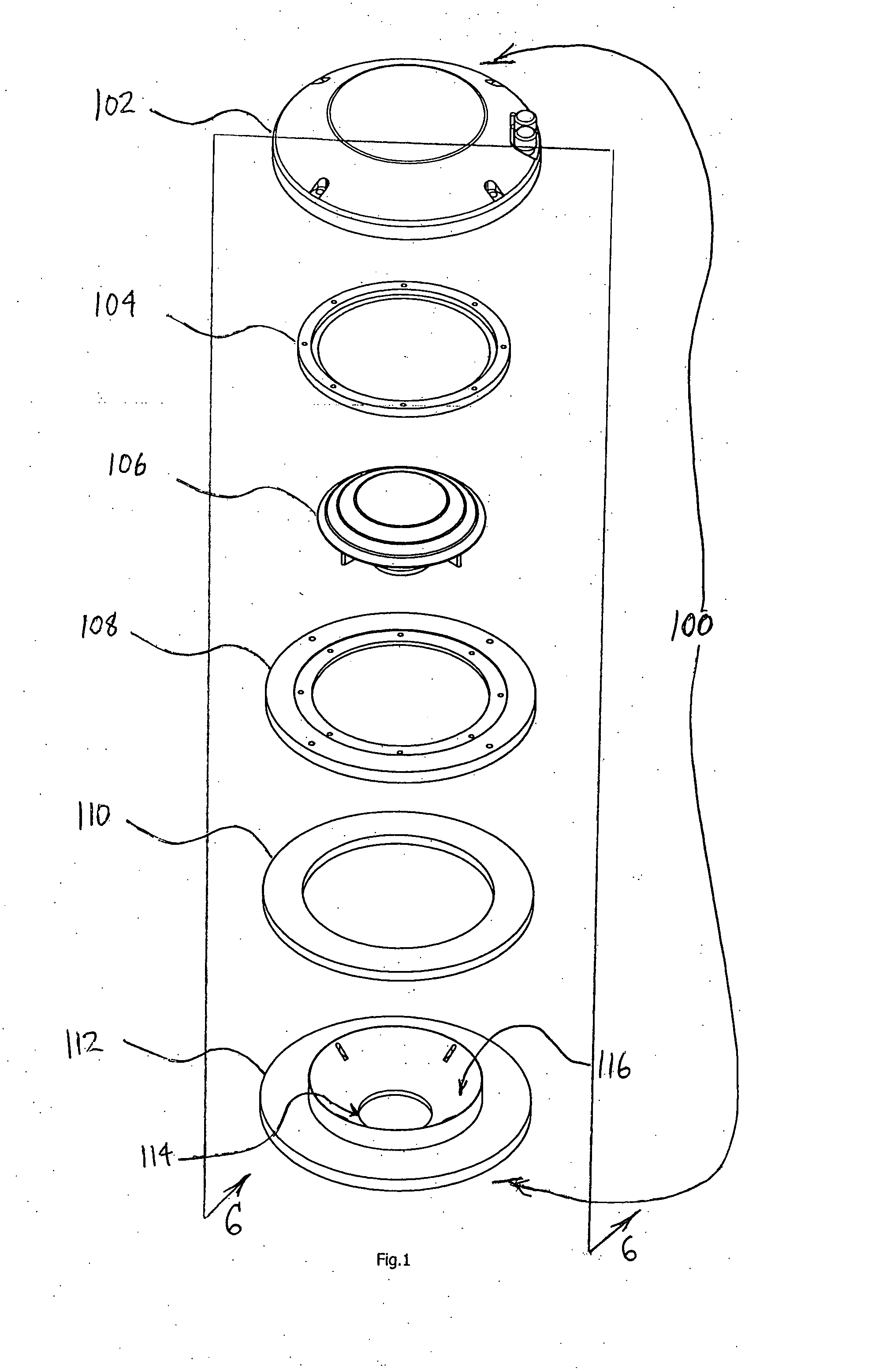
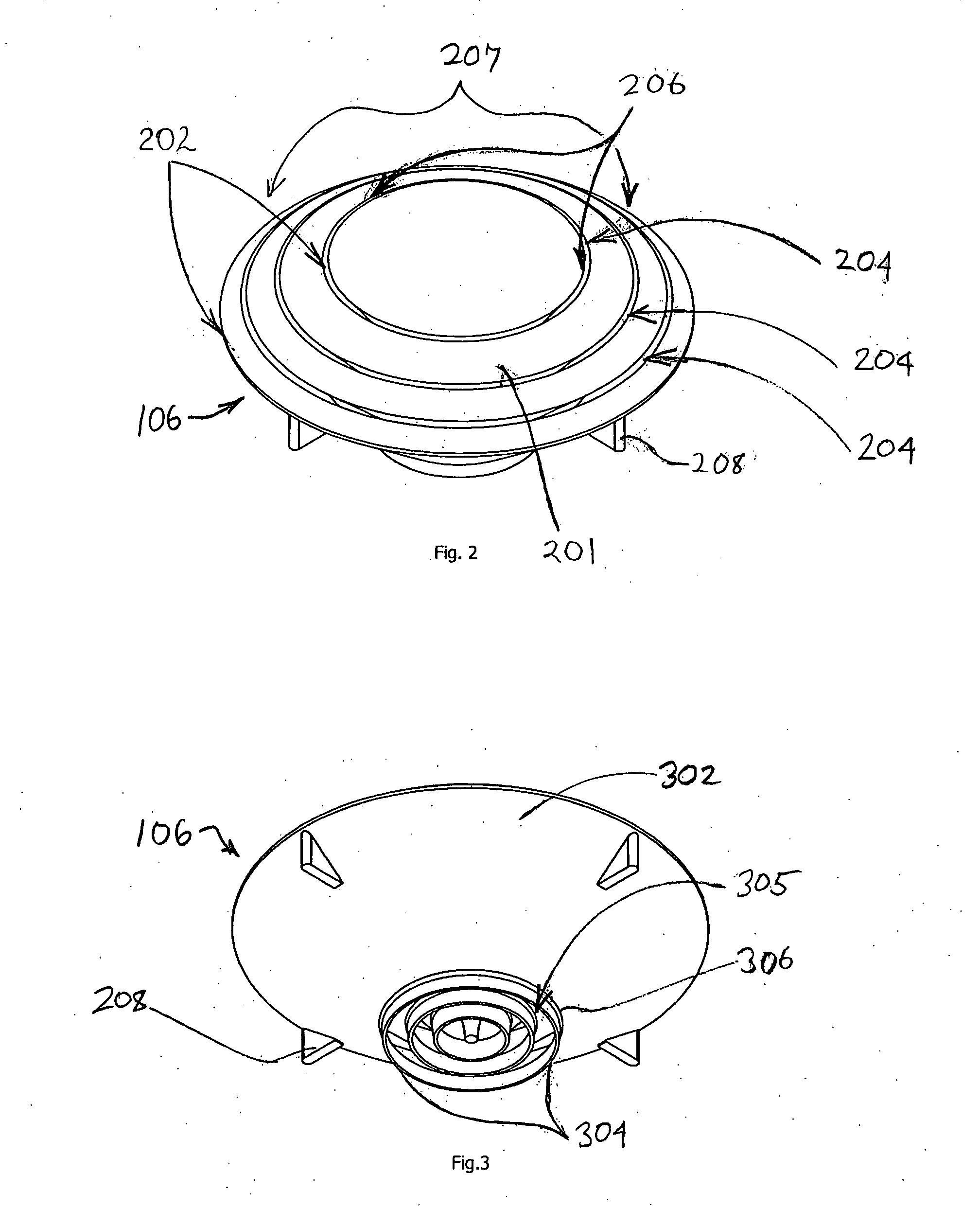
[0038]FIGS. 1 illustrates one embodiment of a compression driver in exploded assembly form. The compression driver comprises a cap 102 that provides both supportive structure and protection for the internal components of the driver. A semi-spherical diaphragm 104 with an integral voice coil (not shown) covers a phasing plug 106. The diaphragm 104 is secured to a top plate 108. The same top plate 108 also captures a permanent magnet 110 between it and a bottom plate 112. The phasing plug 106 is positioned between the bottom plate 112 and the diaphragm 104 and provides an acoustical conduit or pathwa...


PUM


Abstract

A phasing plug for use in a compression driver is configured with a central sound absorbing region that absorbs phase-distorted sound waves produced by an adjacent region of a vibrating diaphragm. The phasing plug is constructed from a plurality of generally hollow frusto-conical rings and a central conical element. The central conical element serves as a sound absorption region for absorbing phase-distorted sound waves. The phasing plug has a plurality of annular inlet apertures that permit sound waves to enter the phasing plug and traverse to an outlet region of the phasing plug. The outlet region is further enhanced by a plurality of wave guide rings that focus the exiting sound waves in a unified direction resulting in the dynamic reproduction and delivery of coherent high-frequency sound waves over a greater distance.

Description

FIELD OF THE INVENTION[0001]The present invention relates to electro-acoustic loudspeakers typically known as compression drivers and, more particularly, to an improved phasing plug for use in such compression drivers.BACKGROUND OF THE INVENTION[0002]Compression drivers transform electrical signals into sound by actuating an internal semi-spherical diaphragm which in turn compresses air that is located between the diaphragm and a phasing plug to produce sound waves. A compression driver is designed to increase the efficiency of a loud speaker by compressing the acoustical energy and transferring it through a channel to the throat of a horn. The compression driver is equipped with a semi-spherical diaphragm which vibrates in response to electrical signals. The electrical signals are applied to a voice coil that is attached to the edge of the diaphragm. The voice coil is arranged such that the coil is concentric with the diaphragm and is immersed in a magnetic field.[0003]Most compres...

Claims


Application Information

Patent Timeline
IPC IPC(8): H04R1/20
CPCH04R23/00
Inventor LEWALLEN, VERNON
Owner LEWALLEN VERNON
Why Eureka
Try Eureka