Spectral measurement apparatus and measurement method utilizing brillouin scattering

a brillouin scattering and measurement method technology, applied in the direction of heat measurement, transmission monitoring, instruments, etc., can solve the problems of slow sensing of a rise in temperature, slow method appearance speed, and troublesome measurement speed of the temperature distribution, etc., to achieve accurate results

Inactive Publication Date: 2008-08-14
SUMITOMO ELECTRIC IND LTD
View PDF19 Cites 16 Cited by
  • Summary
  • Abstract
  • Description
  • Claims
  • Application Information

AI Technical Summary

Benefits of technology

[0022]In the above constitution, because the pumping light and probe light are alternately outputted from one light source, the frequency difference can be finely controlled. Further, the pumping light and probe light outputted from the light source are split by the first coupler and the timing with which the pumping light and probe light enter the optical fiber can be adjusted as a result of th...

Problems solved by technology

In this case, the measurement speed of the temperature distribution is problematic.
Because the measurement speed of the method appearing in the above-menti...

Method used


Image

  • Spectral measurement apparatus and measurement method utilizing brillouin scattering
  • Spectral measurement apparatus and measurement method utilizing brillouin scattering
  • Spectral measurement apparatus and measurement method utilizing brillouin scattering

Examples


Embodiment Construction

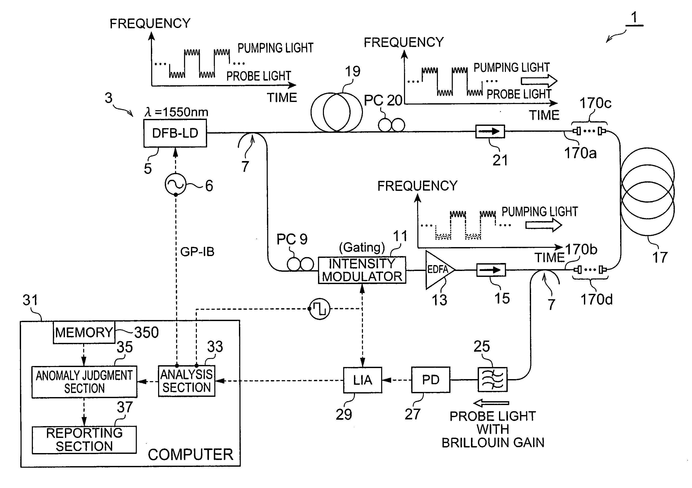
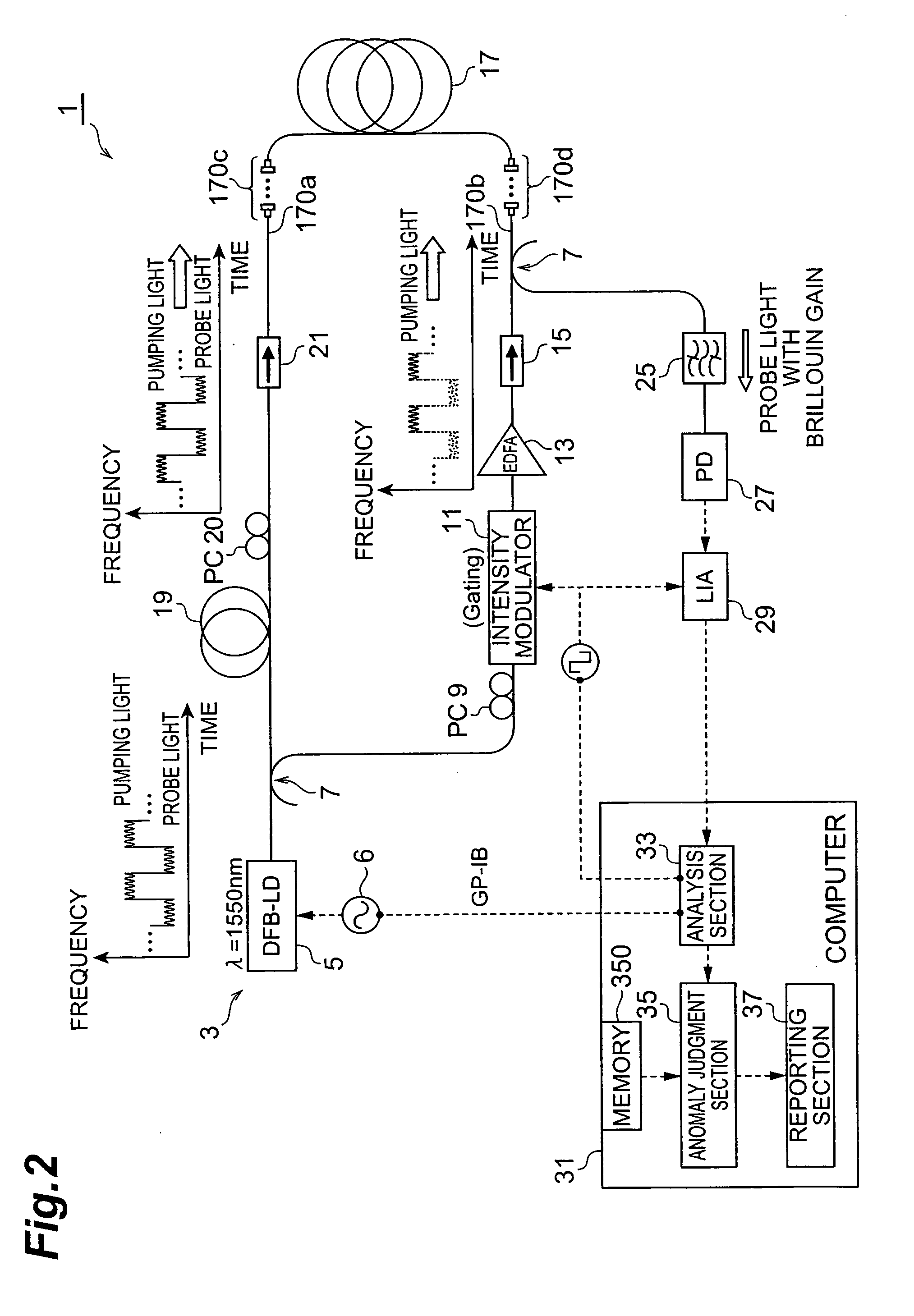
[0038]In the following, embodiments of a spectral measurement apparatus and measurement method utilizing Brillouin scattering the present invention will be explained in detail with reference to FIGS. 1 to 12. In the description of the drawings, identical or corresponding components are designated by the same reference numerals, and overlapping description is omitted.

[0039]The spectral measurement apparatus according to the present invention is an apparatus which senses anomalies in the temperature distribution or strain distribution of an object by utilizing the Brillouin scattering phenomenon, and emit an alarm signal. The spectral measurement method according to the present invention is implemented by utilizing this kind of spectral measurement apparatus. The Brillouin scattering phenomenon is a phenomenon whereby, when light (pumping light) is propagated within an optical fiber, an acoustic wave is generated within the fiber by the pumping light and, as a result of the interactio...


PUM


Abstract

The present invention relates to a spectral measurement apparatus and measurement method utilizing Brillouin scattering, which judge the state of the temperature or strain of an optical fiber more quickly. The spectral measurement apparatus comprises a light source, an analysis section, and an anomaly judgment section. The light source outputs pumping light and probe light. The pumping light and probe light thus output are caused to enter in opposite directions to the sensing fiber. The analysis section analyzes the gain received by the probe light as a result of the Brillouin scattering. The anomaly judgment section judges the state relating to the temperature or strain of the sensing fiber on the basis of the analysis result of the analysis section. The frequency difference υ between the pumping light and probe light is set within a predetermined frequency difference setting range. The frequency difference setting range is a range which includes the frequency difference at which the peak value of the reference gain spectrum of the gain received by the probe light is obtained when the temperature or strain of the sensing fiber is in the reference state and is set at or below the line width of the reference gain spectrum

Description

BACKGROUND OF THE INVENTION[0001]1. Field of the Invention[0002]The present invention relates to a spectral measurement apparatus and measurement method utilizing Brillouin scattering which is generated in an optical fiber to judge the state of the temperature of the optical fiber or the strain of the optical fiber (to sense an anomaly).[0003]2. Related Background Art[0004]The Brillouin gain spectrum (referred to as the ‘BGS’ hereinbelow), representing the gain which is obtained as a result of the Brillouin scattering generated in the optical fiber, changes in accordance with the temperature and strain of the optical fiber. Technology that utilizes this change in the BGS to measure the temperature or strain of the optical fiber is known.[0005]The document (Kazuo Hotate and Sean Ong Soon Leng, “A Correlation-Based Continuous-Wave technique for measurement of dynamic strain along an optical fiber using Brillouin scattering with fully distributed ability”, Technical Digest of OFS-15, P...

Claims


Application Information

Patent Timeline
IPC IPC(8): H04B10/08G01B11/16G01D5/26G01D5/353G01K11/12G01M11/00G01V8/16
CPCG01K11/32G01K2011/322G01K2203/00G01M11/39G01M11/088G01M11/319G01L1/242G01K11/322
Inventor YAMAMOTO, YOSHINORI
Owner SUMITOMO ELECTRIC IND LTD
Why Eureka
Try Eureka