Roots-type fluid machine

a fluid machine and root-type technology, applied in the direction of machines/engines, rotary/oscillating piston pump components, liquid fuel engines, etc., can solve the problems of fluid leakage between the rotor housing and the rotor, and achieve the effect of reducing the pulsation of the suction

Inactive Publication Date: 2008-08-14
TOYOTA IND CORP
View PDF5 Cites 5 Cited by
  • Summary
  • Abstract
  • Description
  • Claims
  • Application Information

AI Technical Summary

Benefits of technology

[0010]Accordingly, it is an objective of the present invention to reduce suction pulsation caused by fluid leakage in a roots-type fluid machine that uses rotors including twisted portions. The twist angle of each twisted portion about the rotation axis of the associated rotor changes linearly or nonlinearly with respect to changes in the position in the axial direction of the rotation axis of the rotor.

Problems solved by technology

However, in the roots-type fluid machine, which is operated without providing oil between the rotor housing and the rotors and between the rotors for lubrication, since a clearance is provided for avoiding sliding contact between the rotor housing and the rotors and between the rotors, fluid leaks between the rotor housing and the rotors and between the rotors.

Method used


Image

  • Roots-type fluid machine
  • Roots-type fluid machine
  • Roots-type fluid machine

Examples


first embodiment

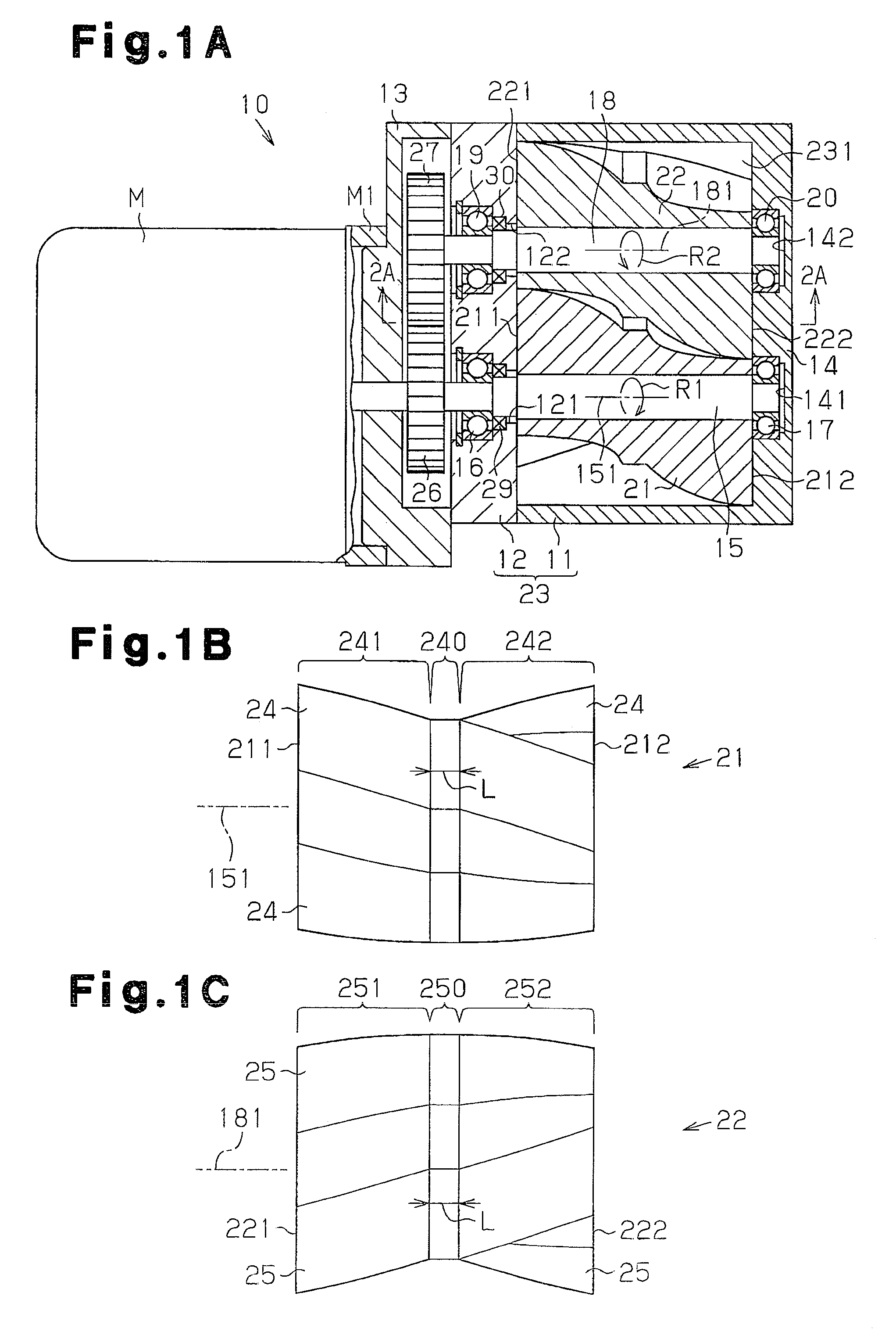
[0047]the present invention will now be described with reference to FIGS. 1A to 3C.

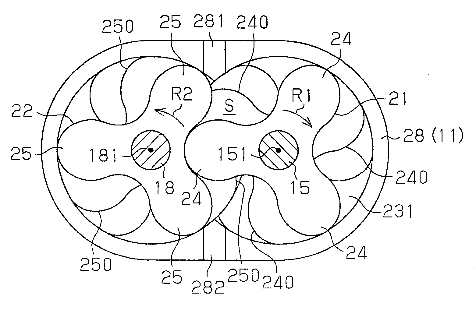
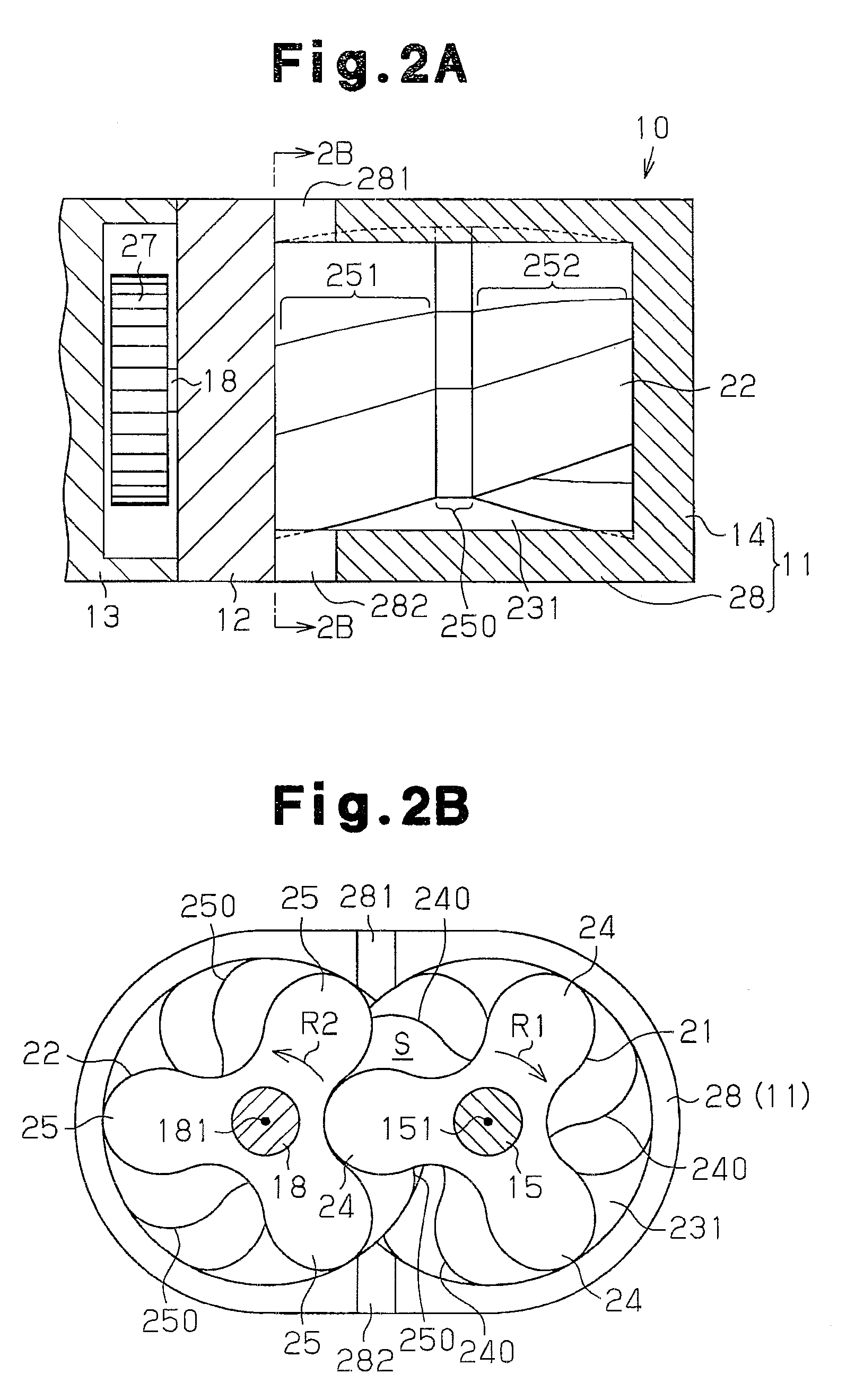
[0048]As shown in FIG. 1A, a partition wall 12 is coupled to the rear end of a front housing member 11, and an electric motor M is coupled to the partition wall 12 with a gear housing member 13. The front housing member 11, the partition wall 12, the gear housing member 13, and a housing member M1 of the electric motor M configure a housing assembly of a roots-type fluid machine 10.

[0049]The front housing member 11 and the partition wall 12 configure a rotor housing 23, which forms a pump chamber 231. A shaft hole 121 extends through the partition wall 12, and a shaft hole 141 is formed in an end wall 14 of the front housing member 11. The end wall 14 of the front housing member 11 and the partition wall 12 rotatably support a rotary shaft 15 of the electric motor M with radial bearings 16, 17 fitted in the shaft holes 121, 141. Similarly, a shaft hole 122 extends through the partition wall 12, and a ...


PUM


Abstract

A roots-type fluid machine including a set of rotors and a rotor housing is disclosed. The rotor housing accommodates the rotors and has a suction space. The set of rotors mesh with each other and rotate in the rotor housing so that fluid is drawn into the suction space and discharged from the rotor housing. Each of the set of rotors includes a tooth having a twisted portion and a different shape variation portion. The twisted portion has a twist angle that changes linearly or non-linearly about a rotation axis of the corresponding rotor with respect to the variation of the position in the direction of the axis. The different shape variation portion has a twisted angle that changes by a smaller degree than the variation of the twist angle of the twisted portion.

Description

BACKGROUND OF THE INVENTION[0001]The present invention relates to a roots-type fluid machine in which a set of rotors mesh with each other and rotate in a rotor housing so that fluid is drawn into a suction space in the rotor housing and discharged from the rotor housing.[0002]A roots-type fluid machine with rotors having helical teeth is disclosed in, for example, Japanese Laid-Open Patent Publication No. 2-227588. The teeth of the rotors are monotonically twisted into helical form around the rotation axes of the rotors. In the roots-type fluid machine that uses helical rotors, the rotors are helically twisted from one end to the other end. When the following equation (1), in which the twist angle of the rotors is expressed by Φ, is satisfied, the volumetric change (the suction amount of fluid to a suction space per unit time) does not fluctuate in the suction space, which is located between the pair of meshed rotors and communicates with an inlet formed in the rotor housing.Φ=(360...

Claims


Application Information

Patent Timeline
Patent Type & Authority Applications(United States)
IPC IPC(8): F04C18/14F04C18/18F04C29/12
CPCF01C1/126F01C1/084
Inventor MASAKI, DAISUKEHIRANO, TAKAYUKINAKANE, YOSHIYUKIYAMADA, KAZUHOFUJII, TOSHIRO
Owner TOYOTA IND CORP
Why Eureka
Try Eureka