

Fast coupling structure of waterproof cable connector
a technology of fast coupling and cable connector, which is applied in the direction of coupling device connection, coupling base/case, securing/insulating coupling contact member, etc., to achieve the effect of easy and quick disassembly of the coupling structur
- Summary
- Abstract
- Description
- Claims
- Application Information
AI Technical Summary
Benefits of technology
Problems solved by technology
Method used
Image

Examples
Embodiment Construction
[0019]Further aspects, objects, and desirable features of the invention will be better understood from the detailed description and drawings that follow in which various embodiments of the disclosed invention are illustrated by way of examples.
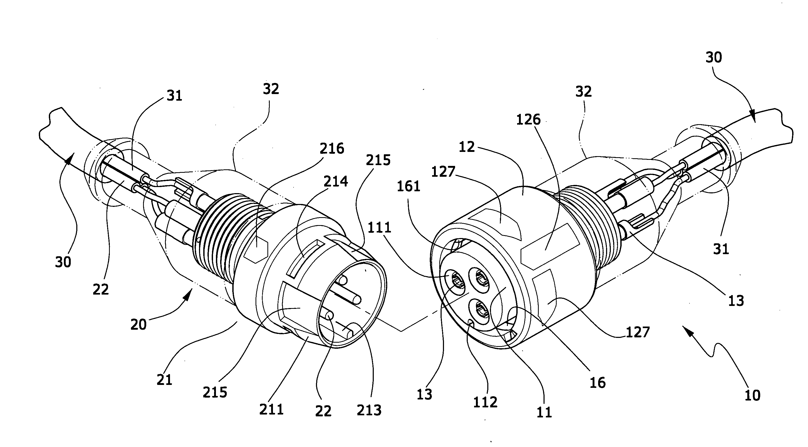
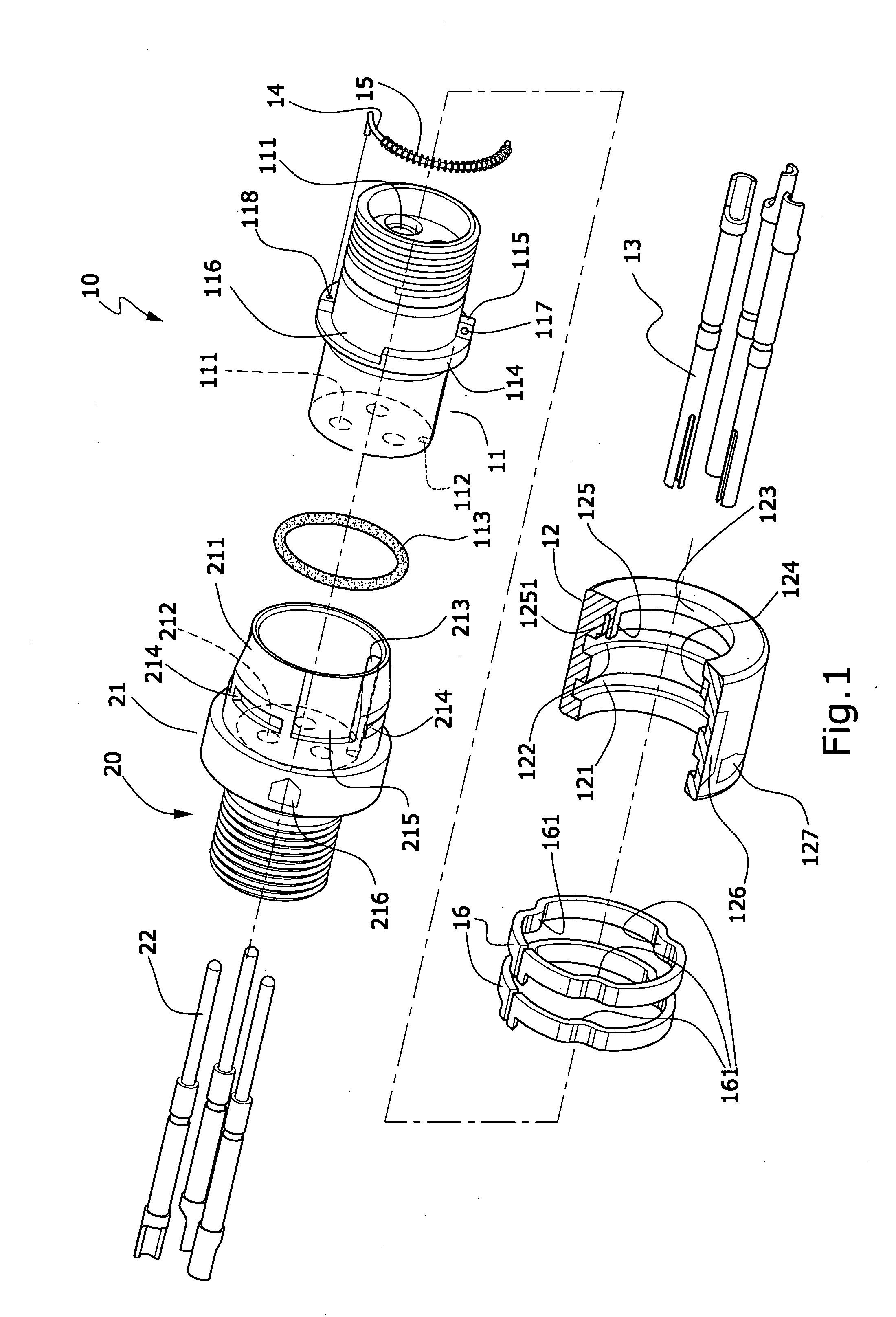
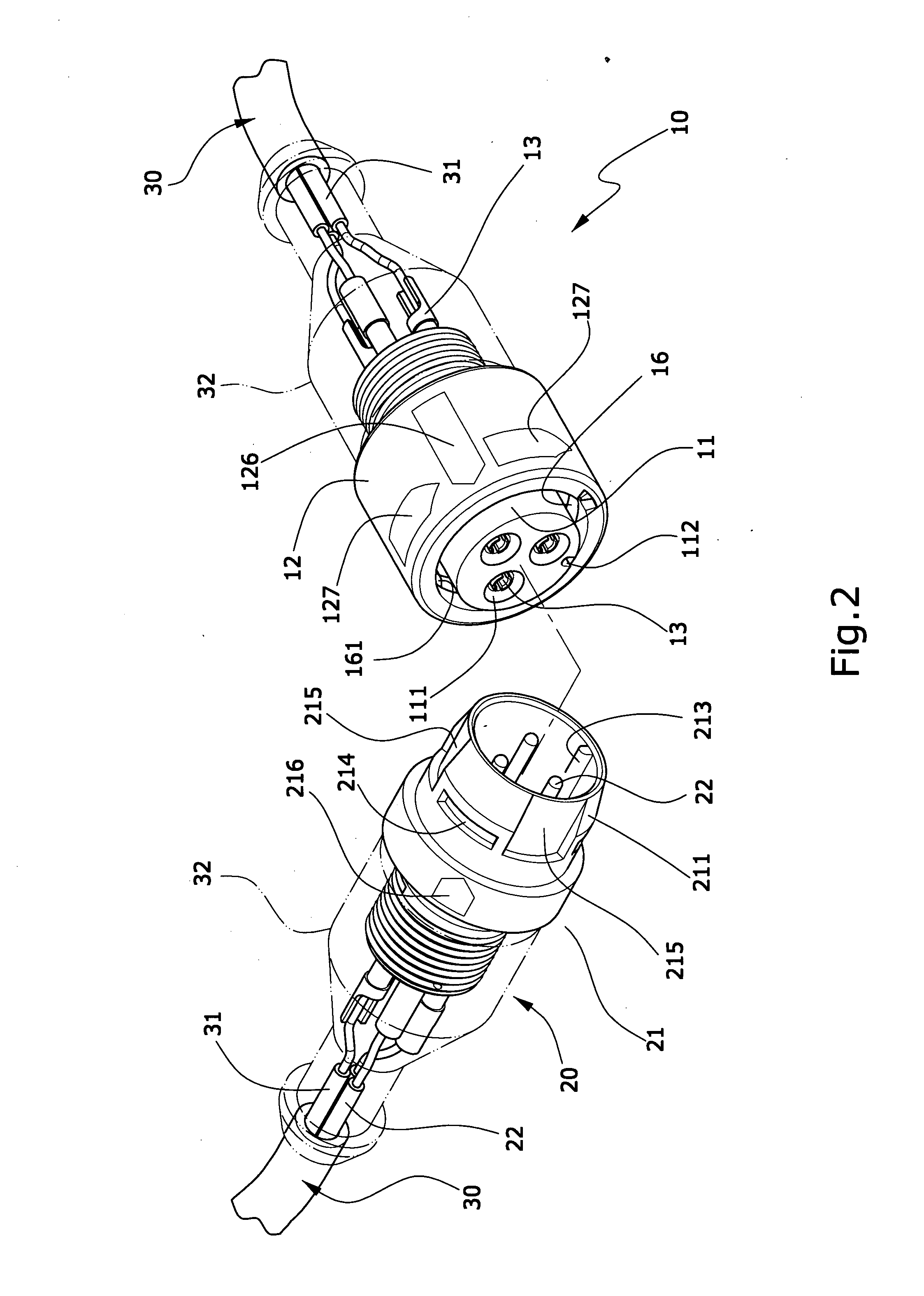
[0020]As shown in FIGS. 1 to 3 that a fast coupling structure of waterproof cable connector of the invention mainly comprises a male connecting joint 10 and a female connecting joint 20 by molding; for connection of electric power source or signals on an electric apparatus, both are fastened on the electric power source or signal transmission end of a cable wire 30. The characteristics can be described as follow.
[0021]The male connecting joint 10 comprises a male housing 11, a cover 12 and a plurality of male connectors 13. The male housing 11 is formed in the shape of a cylinder, having a plurality of terminal holes 111 disposed inside thereof and a longitudinal groove 112 disposed on the outer surface of the front thereof. The longitudinal g...
PUM
 Abstract
Description
Claims
Application Information