Bicycle rear derailleur

Inactive Publication Date: 2008-08-14
SHIMANO INC
View PDF5 Cites 12 Cited by
  • Summary
  • Abstract
  • Description
  • Claims
  • Application Information

AI Technical Summary

Benefits of technology

[0012]One object of the present invention is to provide a bicycle rear derailleur that makes it diffi

Problems solved by technology

When a sprocket rotates in the forward direction in a state in which the chain slip prevention part is caught between the teeth, the inside plate member may be forcibly moved by the sprocket, and there is a danger that the rear derailleur will be broken.
Specifically, when an upshifting operation is performed in a state in which t

Method used


Image

  • Bicycle rear derailleur
  • Bicycle rear derailleur
  • Bicycle rear derailleur

Examples


Embodiment Construction

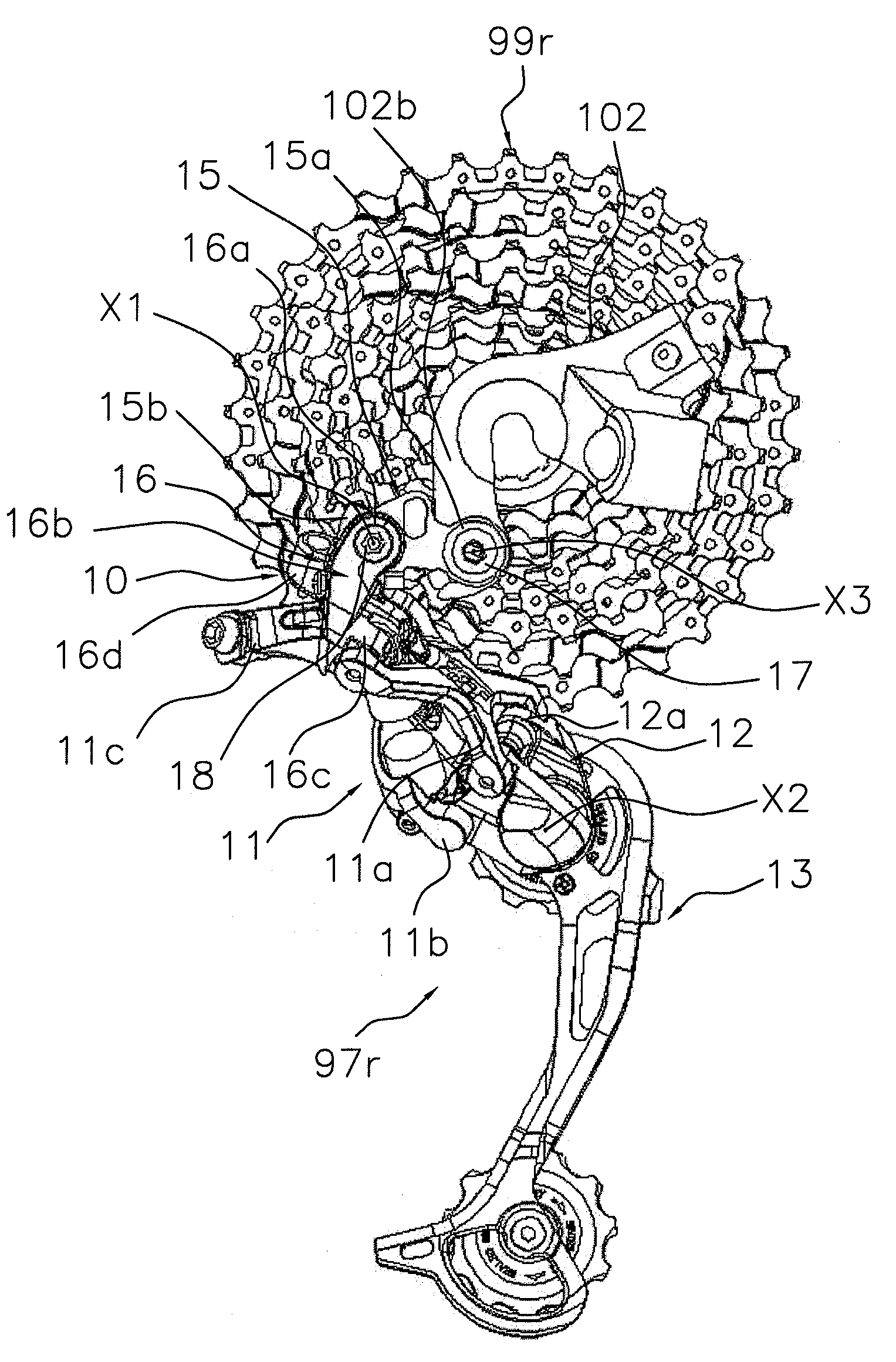
[0041]Selected embodiments of the present invention will now be explained with reference to the drawings. It will be apparent to those skilled in the art from this disclosure that the following descriptions of the embodiments of the present invention are provided for illustration only and not for the purpose of limiting the invention as defined by the appended claims and their equivalents.

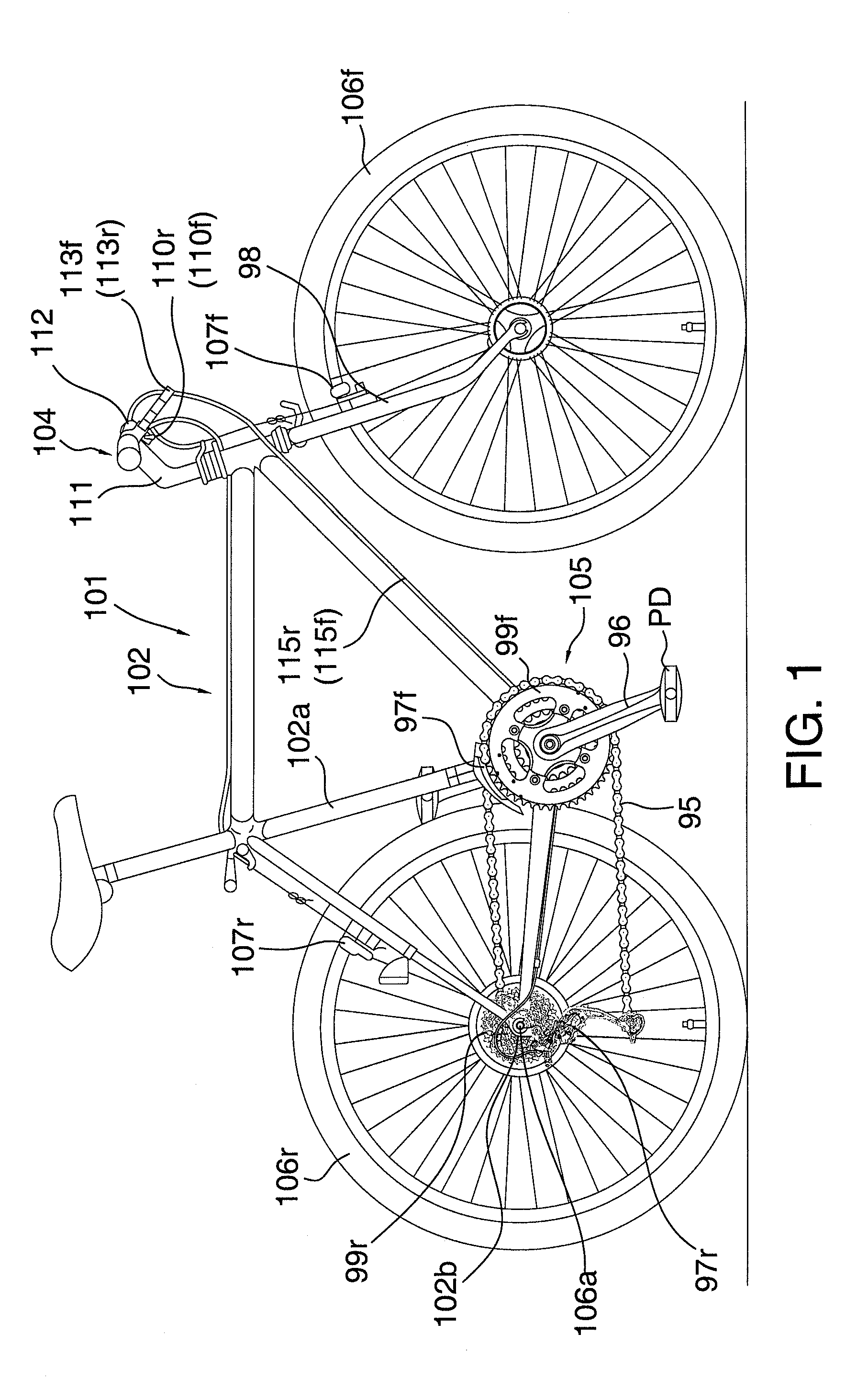
[0042]Referring initially to FIG. 1, a bicycle 101 is illustrated with a rear derailleur 97r in accordance with one embodiment of the present invention. In the illustrated embodiment, the bicycle 101 is a mountain bike for off-road use. The bicycle 101 basically includes a frame 102, a drive train (component) 105, front and rear wheels 106f and 106r, front and rear brake devices 107f and 107r, and a pair of (front and rear) gearshift operating parts 110f and 110r. The frame 102 has diamond shape. A front fork 98 is pivotally coupled to the frame 102 and a handlebar component 104 is fixedly attached...


PUM


Abstract

The chain guide of a bicycle rear derailleur is a chain guide which is connected to a movable member so that this guide is free to swing about a center pivot axis. The chain guide has a pair of plate members rotatably supporting a guide pulley and a tension pulley. One of the plate members is provided with a chain slip prevention part which is disposed between both plate members in the vicinity of the guide pulley. Preferably, the chain slip prevention part has a width of ten mm or greater and fifty mm or less.

Description

CROSS-REFERENCE TO RELATED APPLICATIONS[0001]This application claims priority under 35 U.S.C. § 119 to Japanese Patent Application No. 2007-030266, filed Feb. 9, 2007. The entire disclosure of Japanese Patent Application No. 2007-030266 is hereby incorporated herein by reference.BACKGROUND OF THE INVENTION[0002]1. Field of the Invention[0003]The present invention relates to a derailleur. More specifically, the present invention relates to a bicycle rear derailleur which is mounted on the frame of a bicycle and which is used to selectively transfer a chain to one of a plurality of sprockets mounted on the rear wheel hub axle.[0004]2. Background Information[0005]Bicycling is becoming an increasingly more popular form of recreation as well as a means of transportation. Moreover, bicycling has become a very popular competitive sport for both amateurs and professionals. Whether the bicycle is used for recreation, transportation or competition, the bicycle industry is constantly improving...

Claims


Application Information

Patent Timeline
IPC IPC(8): B62M9/12B62M9/126
CPCB62M9/128B62M9/126
Inventor KUNISAWA, SATORU
Owner SHIMANO INC
Why Eureka
Try Eureka