Dynamic spinal stabilization device

a stabilization device and dynamic technology, applied in the field of spinal prosthesis, can solve the problems of spinal instability, insufficient replacement of degenerative discs, and many individuals may develop severe lower back pain, and achieve the effects of reducing any additional strain, resisting and/or dampening the flexion and extension force, and reducing the natural movemen

Inactive Publication Date: 2008-08-14
SPINADYNE
View PDF70 Cites 70 Cited by
  • Summary
  • Abstract
  • Description
  • Claims
  • Application Information

AI Technical Summary

Benefits of technology

[0009]The present invention provides a dynamic stabilization device providing a minimum reduction in the natural movement of the motion segment and reducing any additional strain on the adjacent level of the spinal column in the individual receiving the stabilization device. Moreover, the present invention provides a dynamic stabilization device able to also resist and / or dampen the flexion and extension forces experienced by the motion segment during movement. The dynamic stabilization device may further provide an arcuate or angular path of movement that closely approximates the arc of motion of a healthy lumbar segment, while also having a selectively adjustable path of motion for a particular application or patient. Furthermore, the present invention provides a dynamic stabilization device which can continuously adjust to a moving centre of rotation of an intervertebral disc prosthesis, or that of the lumbar disc anteriorly.

Problems solved by technology

While many individuals may simply experience minor sprains or strains that may be somewhat limiting, numerous individuals may develop severe lower back pain caused by inflammatory changes in the lumbar disc associated with such changes.
However, the replacement of a degenerative disc may not suffice, as the facet joint components of the spinal column may still be a source of discomfort and / or limited mobility.
This often makes the spine unstable, requiring stabilization of the spine after the decompression.
A posterior dynamic stabilization device is typically attached to pedicle screws inserted in to the vertebrae, however, conventional devices are limited in their allowable range of motion and results may vary from patient to patient.
If the spine is altered in any way, such as with disc and facet degeneration or spinal implantation, this center of rotation shifts, leading to undesirable consequences, such as further degradation, limited movement ability, etc.

Method used


Image

  • Dynamic spinal stabilization device
  • Dynamic spinal stabilization device
  • Dynamic spinal stabilization device

Examples


Embodiment Construction

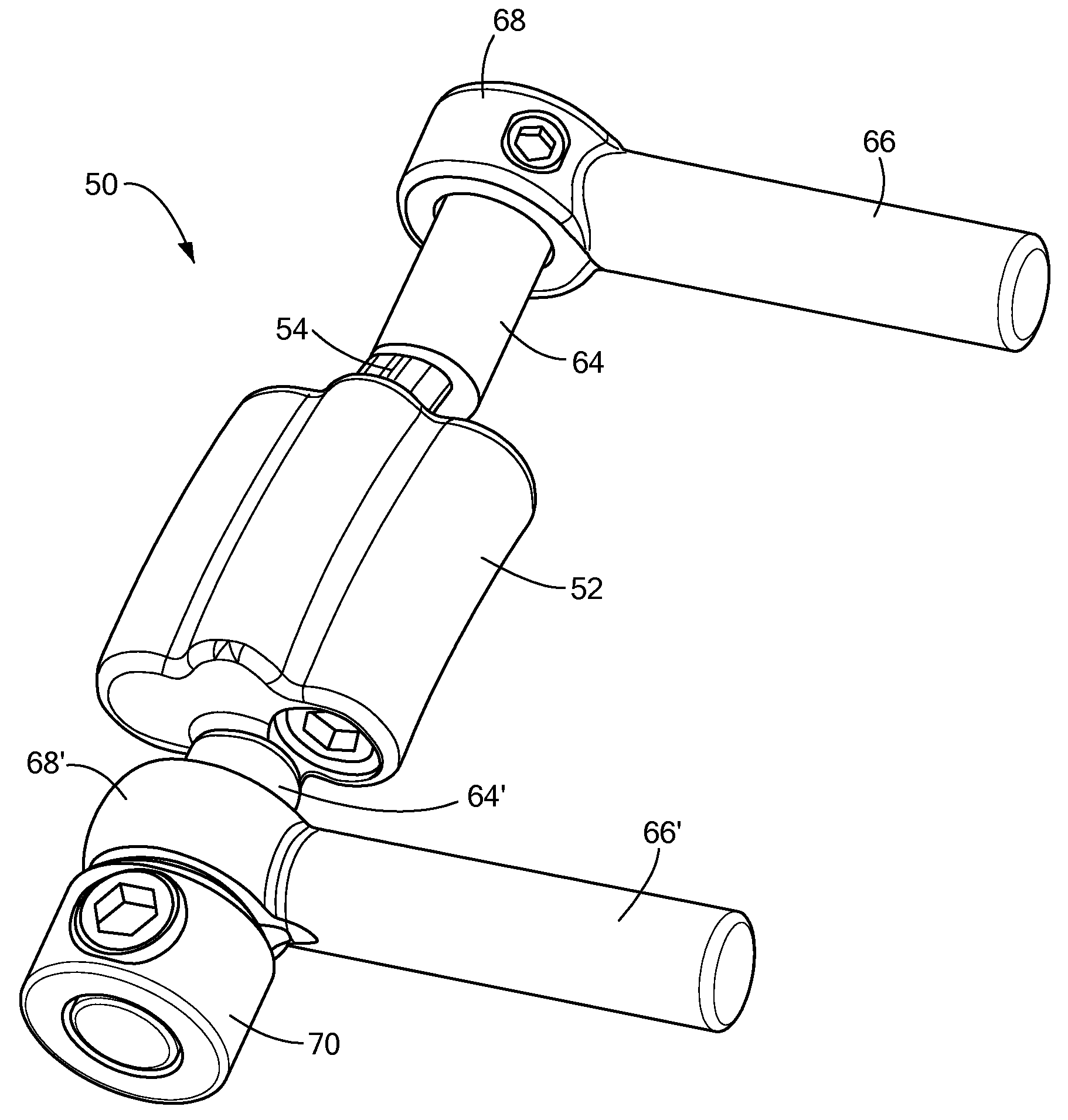
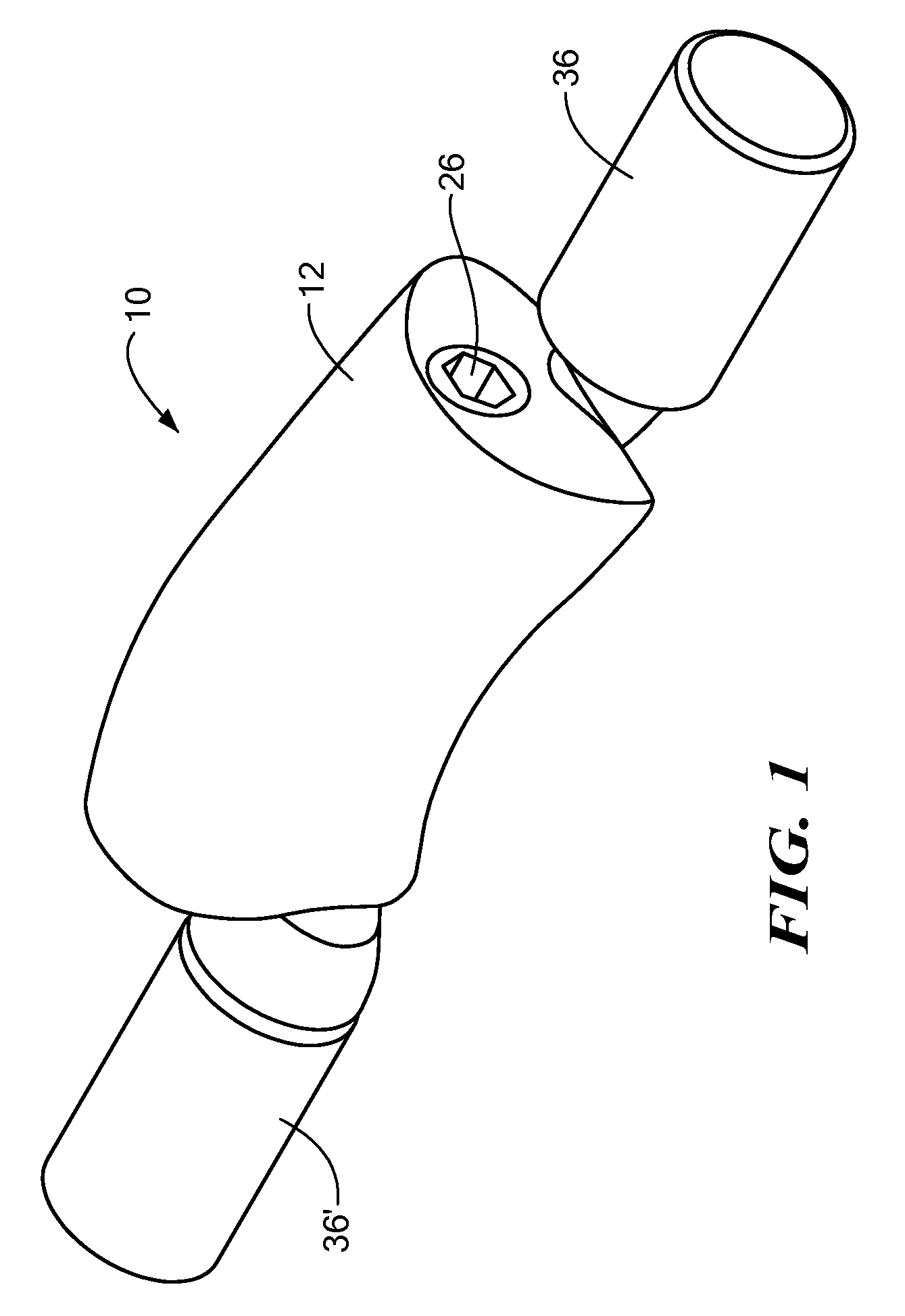
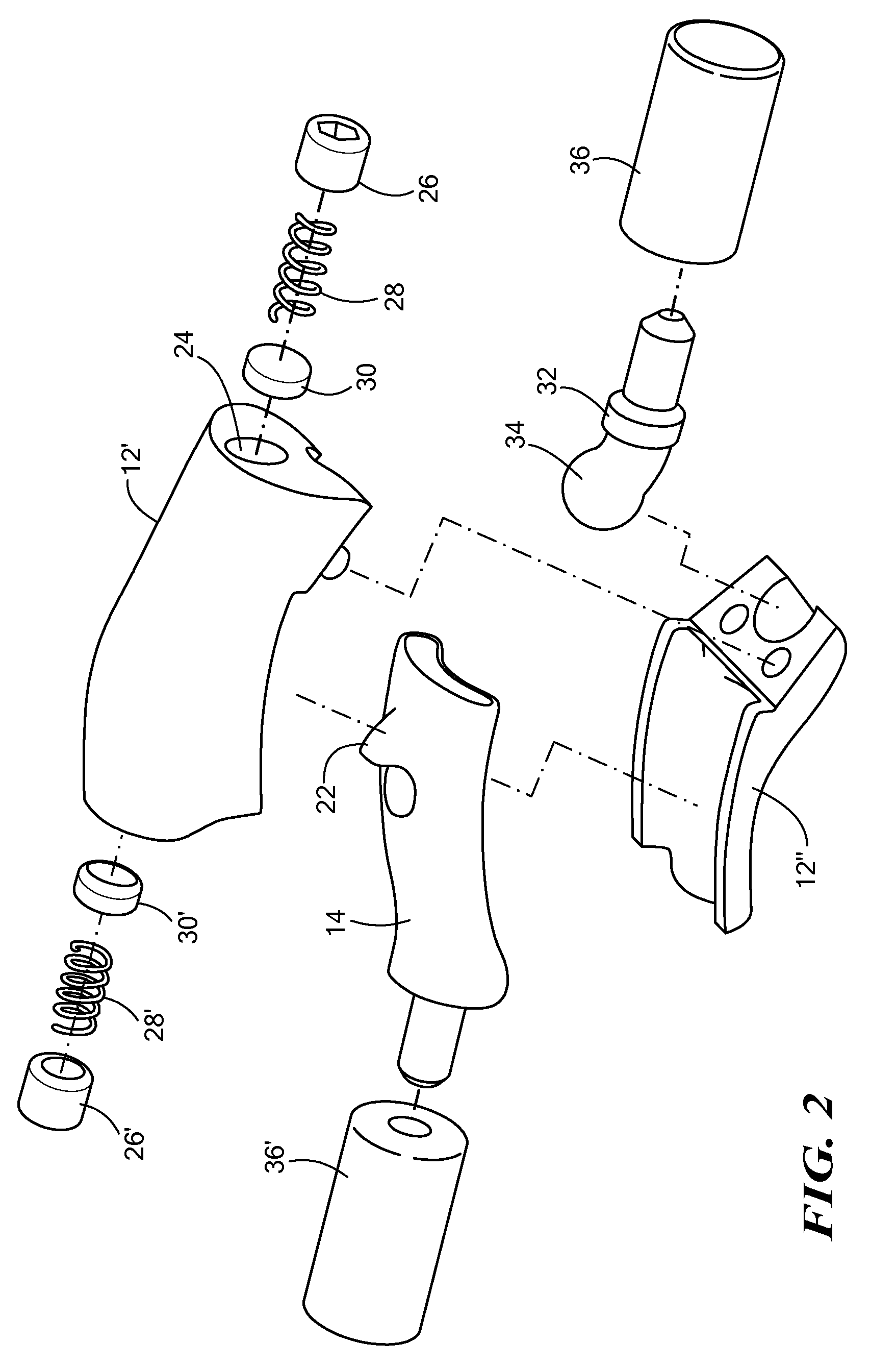
[0033]The present invention provides a dynamic stabilization device 10 positionable about a portion of a spinal column. Now referring to FIGS. 1-3, the present invention provides a stabilization device 10 generally including a first component 12 and a second component 14, where the first and second components are movably coupled to one another to define a range or path of motion therebetween. As used herein, the term “path of motion” is intended to include a length, distance and / or shape associated with the movement of either and / or both the first and second components. The motion of the first and second components may include an arcuate path about which the first and second components are able to articulate, where the arcuate path may define a point of rotation about which the first and second components move.

[0034]In particular, the first component 12 may include a body defining an opening providing access to a first cavity or recessed region 16, where the first cavity 16 is able ...


PUM


Abstract

The present invention provides a dynamic stabilization device positionable about a portion of a spinal column. The stabilization device may generally include a first component and a second component, where the first and second components are movably coupled to one another to define an arcuate path of motion. The stabilization device may also include one or more adjustment elements positionable within first and second adjustment openings to affect the path of motion between the first and second components and/or the behavior and characteristics of the movement. In addition, one or more resistive elements may be adjustably positionable within either and/or both of the first and second adjustment openings to provide resistance and/or dampening of the forces experienced as the first and second components move relative to one another. The stabilization device may further define a joint having three degrees of freedom to adapt to movement of a spinal column.

Description

CROSS-REFERENCE TO RELATED APPLICATION[0001]This application is a continuation-in part of pending utility application Ser. No. 11 / 728,204, filed Mar. 23, 2007, entitled DYNAMIC SPINAL STABILIZATION DEVICE, which Application is related to and claims priority to U.S. Provisional Patent Application Ser. No. 60 / 847,069, filed Sep. 25, 2006, entitled PROSTHETIC FACET JOINT COMPONENT, and U.S. Provisional Patent Application Ser. No. 60 / 811,843, filed Jun. 8, 2006, entitled PROSTHETIC FACET JOINT, the entirety of each of which is incorporated herein by reference.STATEMENT REGARDING FEDERALLY SPONSORED RESEARCH OR DEVELOPMENT[0002]n / aFIELD OF THE INVENTION[0003]The present invention relates generally to spinal prostheses, and more particularly, towards a method and system for stabilization of a spinal segment.BACKGROUND OF THE INVENTION[0004]A significant portion of the population has experiences pain or discomfort resulting from spinal injuries or degenerative conditions in and around the ...

Claims


Application Information

Patent Timeline
Patent Type & Authority Applications(United States)
IPC IPC(8): A61B17/58
CPCA61B17/7001A61B17/7004A61B17/7014A61B17/7023A61F2/442A61B17/7032A61B17/7041A61B17/7049A61B17/7064A61B17/7025
Inventor BROWN, STEVENKRISHNA, MANOJFRIESEM, TAIFERNANDEZ, JOSE
Owner SPINADYNE
Why Eureka
Try Eureka