
Perception model for trajectory following autonomous and human augmented speed control

Active Publication Date: 2008-08-14
DEERE & CO
View PDF98 Cites 23 Cited by
  • Summary
  • Abstract
  • Description
  • Claims
  • Application Information

AI Technical Summary

Benefits of technology

[0007]The present invention provides a trajectory following autonomous speed control system for the speed control of a vehicle.
[0008]The invention comprises, in one form thereof, a speed control method of a vehicle including the steps of obtaining a steering angle, a velocity error and a distance error. The velocity and the distance errors be

Problems solved by technology

For example, pilots, even after extensive training on a particular aircraft, do not qualify for piloting a similar aircraft, without extensive training on the alternate aircraft.
Agricultural machinery has become more expensive and complex to operate.
Traditionally, human machine control has been limited to open-loop control design methods, where the human operator is assumed to receive appropriate feedback and perform adequate compensation to ensure that the machines function as required and to maintain stable operation.
These approaches do not always translate to the best quantitative design or overall human-machine synergy.
Assuming that an individual expert operator is the only method of ensuring qualitative response presents several problems.
One problem with this assumption is that humans are not the same, with varying perceptions, experience, reaction time, response characteristics and expectations from the machine.
The result may be a perceived lack in the qualitative aspects of the human machine interface for some operators.
The task of designing optimal human-machine system performance without a consistent operator becomes a daunting one, as there are no methods for setting appropriate constraints.
The result is that qualitative design change effectiveness is not guaranteed since they are applied based on an operator's continuously adapting perception of the machine performance.

Method used


Image

  • Perception model for trajectory following autonomous and human augmented speed control
  • Perception model for trajectory following autonomous and human augmented speed control
  • Perception model for trajectory following autonomous and human augmented speed control

Examples


Embodiment Construction

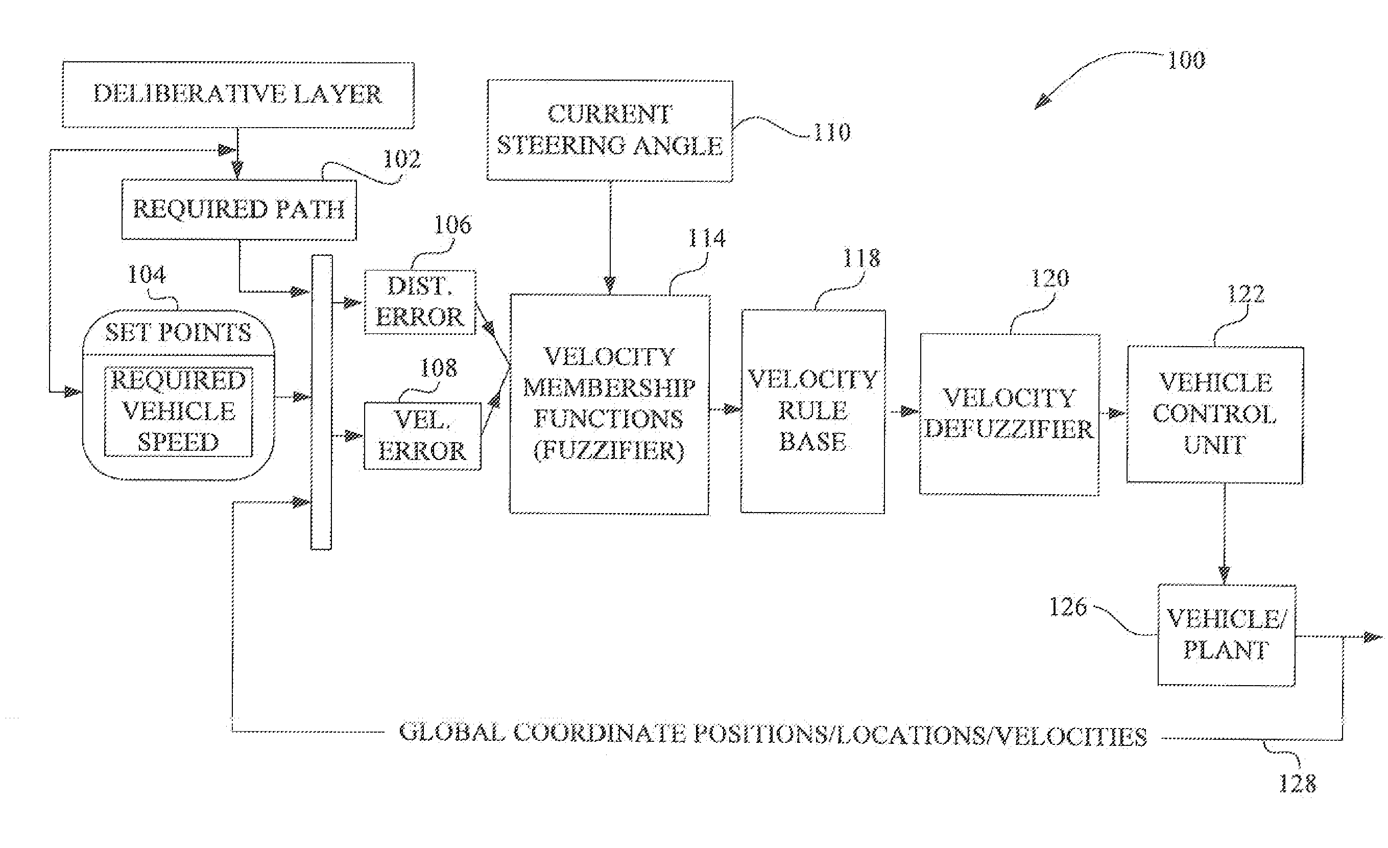
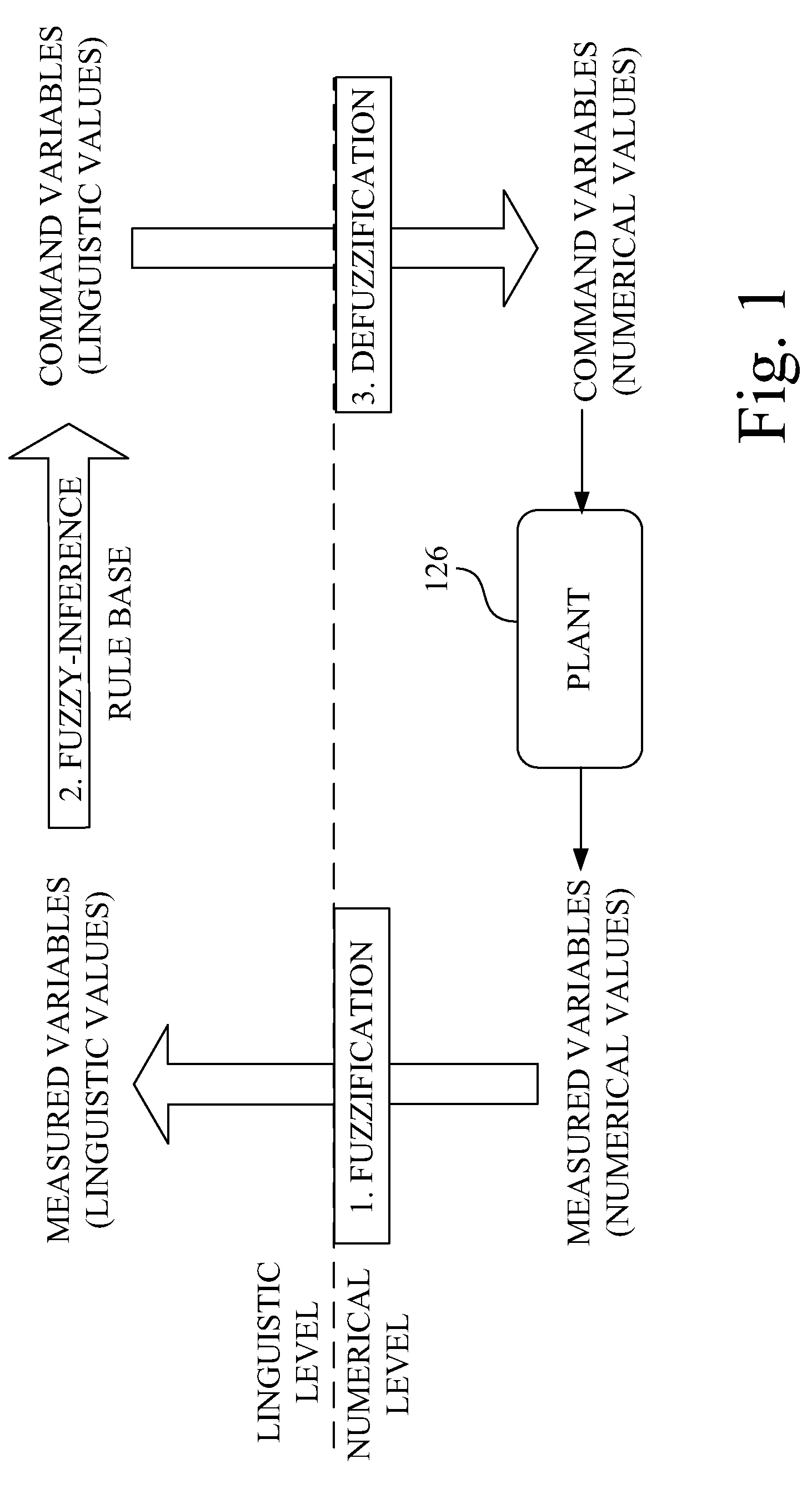
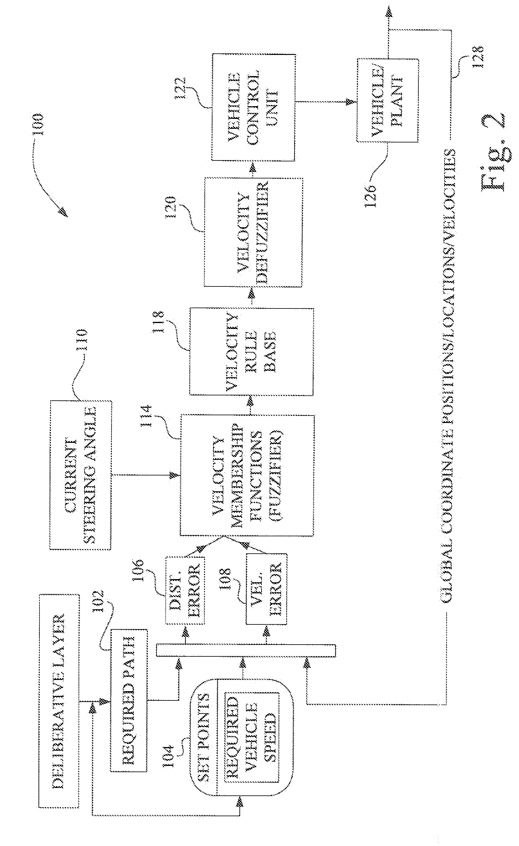
[0019]Referring now to the drawings, and more particularly to FIGS. 1 and 2, there are shown schematic illustrations of an approach used in an embodiment of a method of the present invention. The goal is to provide for a trajectory following autonomous speed control and / or human augmented speed control functions, which is undertaken by the use of a fuzzy logic controller structure. The autonomous speed control includes the fuzzification of the input variables, the application of the variables to a fuzzy inference and rule base construction, and the defuzzification of the output variables. The fuzzification step converts control inputs into a linguistic format using membership functions. The membership functions are based on the outputs from an error interpreter. The input variables to the model include several performance related measurable items. To reduce computational effort, linear approximations are implemented. A fuzzy membership function for the various linguistic variables a...


PUM


Abstract

A speed control method of a vehicle including the steps of obtaining a steering angle, a velocity error and a distance error. The velocity and the distance error being determined by mathematical combinations of a GPS position, a required path and speed set points. The steering angle, velocity errors and distance error are applied to fuzzy logic membership functions to produce an output that is applied to a velocity rule base. An output from the velocity rule base is defuzzified to produce a speed signal.

Description

FIELD OF THE INVENTION[0001]The present invention relates to a method of speed control, and, more particularly to an autonomous speed control of a vehicle.BACKGROUND OF THE INVENTION[0002]Automatic control of complex machinery, such as moving vehicles exists, for example, the control systems for aircraft autopilots. Just as a man-machine interface is required for the man to control the machinery an automation of the control system is largely specific to the particular machinery that is to be controlled. For example, pilots, even after extensive training on a particular aircraft, do not qualify for piloting a similar aircraft, without extensive training on the alternate aircraft.[0003]Agricultural machinery has become more expensive and complex to operate. Traditionally, human machine control has been limited to open-loop control design methods, where the human operator is assumed to receive appropriate feedback and perform adequate compensation to ensure that the machines function a...

Claims


Application Information

Patent Timeline
IPC IPC(8): B60T7/12
CPCG05D1/0223B60W2050/0057
Inventor NORRIS, WILLIAM ROBERTROMIG, BERNARD EDWINREID, JOHN FRANKLIN
Owner DEERE & CO
Learn More