
Device and method for displaying delay analysis results, and computer product

a delay analysis and delay margin technology, applied in static indicating devices, instruments, program control, etc., can solve the problems of increasing design load, ssta may not give enough information to understand which path or circuit element of the circuit, and increasing the difficulty of timing design

Inactive Publication Date: 2008-08-14
FUJITSU LTD
View PDF13 Cites 6 Cited by
  • Summary
  • Abstract
  • Description
  • Claims
  • Application Information

AI Technical Summary

Benefits of technology

[0012]It is an object of the present invention to at least

Problems solved by technology

In conventional static timing analysis (STA), although ample delay margin is secured for these circuit delay fluctuations, timing design is becoming more difficult with expanding delay margins.
By the conventional technique, however, an analysis result obtained by SSTA may not give enough information to understand which path or circuit element of the circuit was affected and how, in terms of the delay of the entire circuit.
For example, without supplementary information, determination of delay dispersion characteristics or a bottleneck circuit element only from a result of numerated values or the like was difficult causing problems such as increased design load and a prolonged design period.
Dispersion of delay by statistical factors is difficult to automatically estimate by SSTA.

Method used


Image

  • Device and method for displaying delay analysis results, and computer product
  • Device and method for displaying delay analysis results, and computer product
  • Device and method for displaying delay analysis results, and computer product

Examples


Embodiment Construction

[0030]Referring to the accompanying drawings, exemplary embodiments according to the present invention are explained in detail below.

[0031]Exemplary embodiments according to the present invention will be explained in detail below with reference to accompanying drawings.

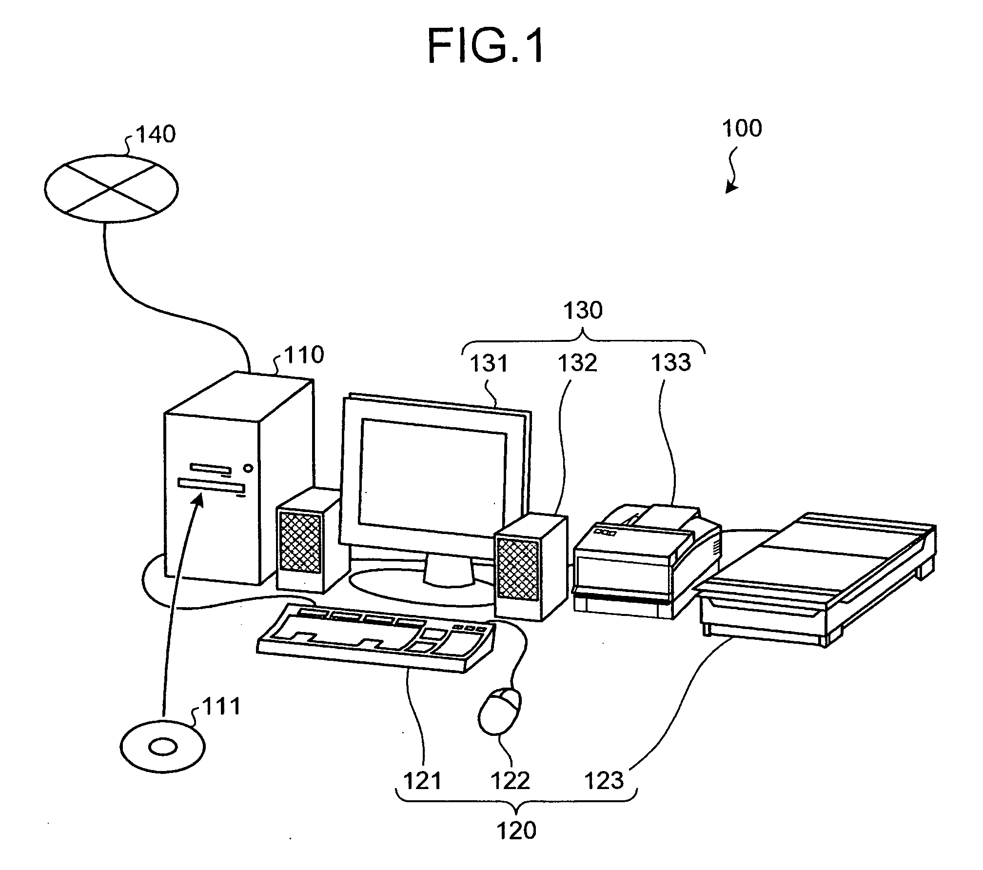
[0032]FIG. 1 is a block diagram of the device according to the embodiment of the present invention. A device 100 for displaying delay analysis results includes a computer main body 110, input devices 120, and output devices 130 and can be connected to a network 140, such as a local area network (LAN), a wide area network (WAN) and the Internet, through a router or modem not shown.

[0033]The computer main body 110 includes a central processing unit (CPU), a memory, and an interface. The CPU is responsible for overall control of the device 100. The memory includes a read-only memory (ROM), a random access memory (RAM), a hard disk (HD), an optical disc 111, and a flash memory. The memory is used as a work area of the CPU...


PUM


Abstract

Fluctuations of cumulative delay value and delay dispersion in a path of a circuit are displayed graphically. Cumulative delay values of circuit elements in the path are obtained from delay analysis results of the circuit and dispersion is obtained from a probability density distribution of the delay of the circuit elements. Corresponding to the location of the circuit element in the path, the former and the latter are plotted on a coordinate plane.

Description

CROSS-REFERENCE TO RELATED APPLICATIONS[0001]This application is based upon and claims the benefit of priority from the prior Japanese Patent Application No. 2007-031867, filed on Feb. 13, 2007, the entire contents of which are incorporated herein by reference.BACKGROUND OF THE INVENTION[0002]1. Field of the Invention[0003]The present invention relates to a technology for displaying delay analysis results.[0004]2. Description of the Related Art[0005]In recent years, with the minimization of integrated semiconductor circuits, the effect of statistical factors such as processing variation, source voltage reduction, and crosstalk has increased, thereby magnifying circuit delay fluctuations. In conventional static timing analysis (STA), although ample delay margin is secured for these circuit delay fluctuations, timing design is becoming more difficult with expanding delay margins.[0006]Hence, needs are rising for statistical static timing analysis (SSTA) that can reduce unnecessary del...

Claims


Application Information

Patent Timeline
IPC IPC(8): G06F3/00
CPCG06F17/5031G06F30/3312
Inventor SHIBUYA, TOSHIYUKIHOMMA, KATSUMINITTA, IZUMI
Owner FUJITSU LTD
Features
  • Generate Ideas
  • Intellectual Property
  • Life Sciences
  • Materials
  • Tech Scout
  • Unparalleled Data Quality
  • Higher Quality Content
  • 60% Fewer Hallucinations
Learn More