Structural column wrap assembly

a wrap assembly and structure technology, applied in the direction of scaffold accessories, washstands, lighting support devices, etc., can solve the problems of difficulty in offsetting, and labor-intensive installation of the wrap assembly, and achieve the effect of easy and inexpensive assembly and easy installation

Inactive Publication Date: 2008-08-21
FYPON
View PDF10 Cites 7 Cited by
  • Summary
  • Abstract
  • Description
  • Claims
  • Application Information

AI Technical Summary

Benefits of technology

[0018]An important advantage of the present construction over prior comparable column wraps is that the present assembly is completely independent of the column which it surrounds enabling it to be placed in various positions with respect to that column. This allows the assembly to be made vertical even though the structural column wi

Problems solved by technology

Those prior column wraps with internal nailing cleats are disadvantaged in that their installation is labor intensive, requiring the proper cutting, aligning and fastening of various separate squaring blocks or cleats.
In addition, the installation of that wrap assembly is labor intensive in that it requires the measuring and attachi

Method used


Image

  • Structural column wrap assembly
  • Structural column wrap assembly
  • Structural column wrap assembly

Examples


Embodiment Construction

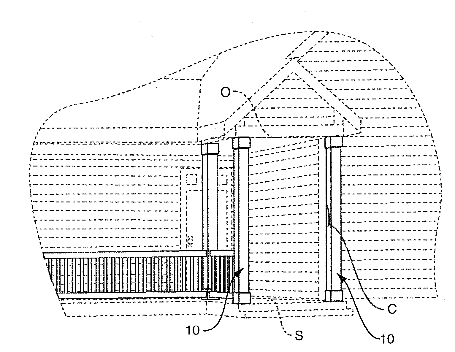
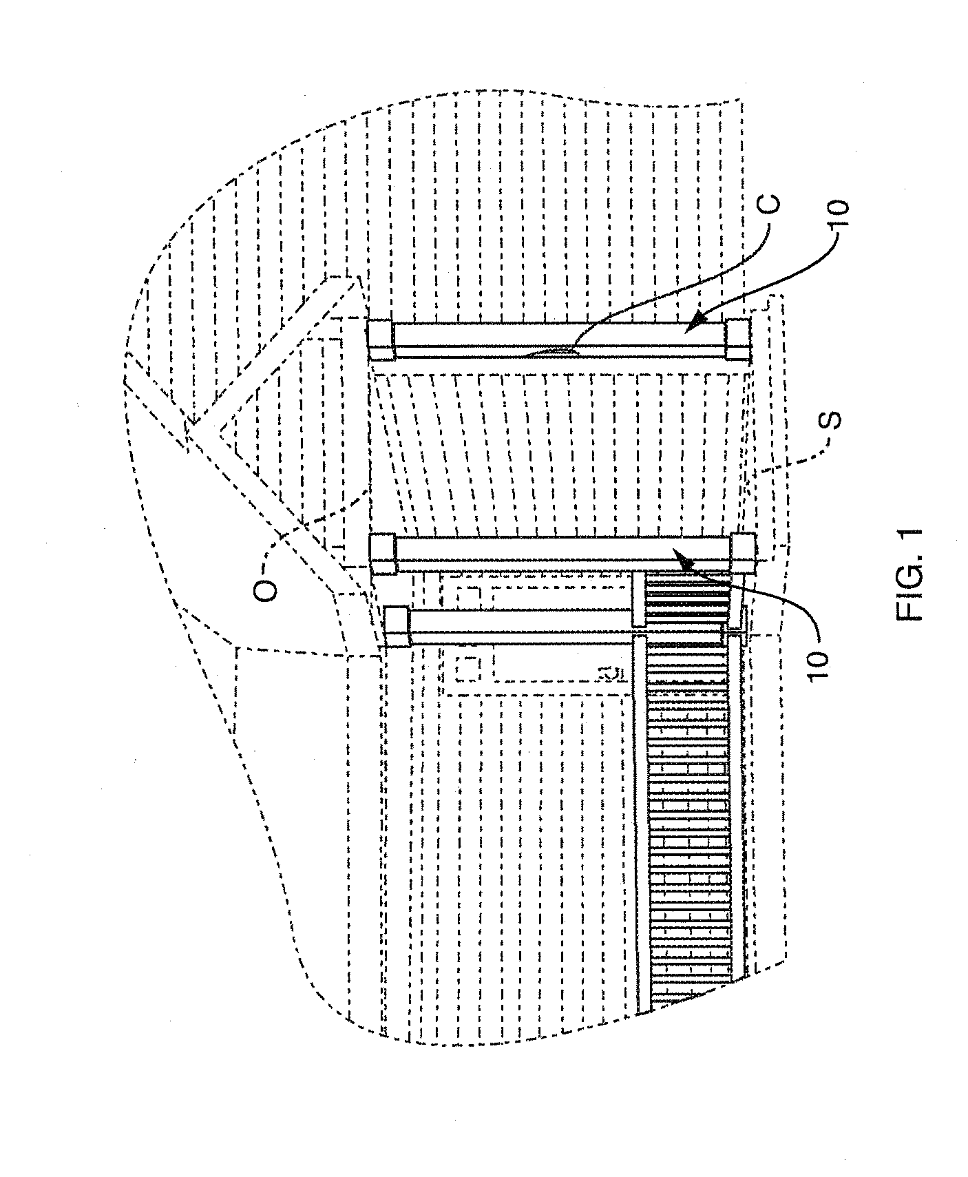
[0025]Referring to the drawing, FIG. 1 illustrates an entryway comprising a plurality of vertical structural or support columns C extending between a support surface S such as a floor or deck and an overhead support O such as a ceiling or beam. Each column C, e.g. a 4×4 in. length of wood, is covered by a column wrap assembly shown generally at 10 which adds apparent girth to the column and provides a smooth, paintable and / or decorative exterior surface around the otherwise unfinished column.

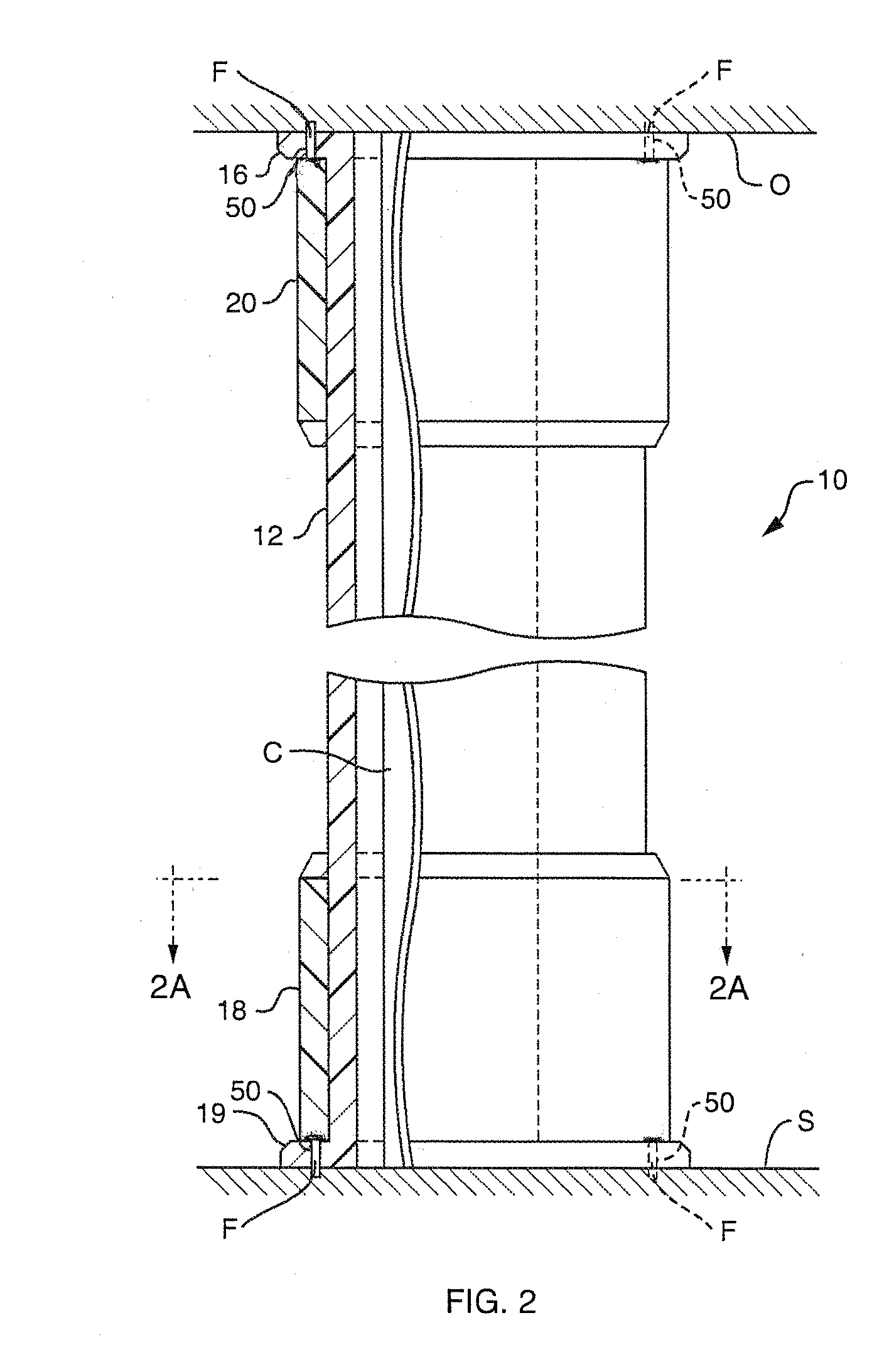
[0026]Referring to FIG. 2, each column wrap assembly 10 comprises a tubular shaft 12 having an integral exterior fastening cleat 14 at its lower end. A second, annular fastening cleat 16 is provided at the upper end of the shaft but which, as we shall see, is separate from the shaft. Suitable fasteners F may be driven through cleats 14 and 16 into support surface S and the overhead support O, respectively, to fix the position of shaft 12 with respect to column C.

[0027]In order to add decorative ...


PUM

PropertyMeasurementUnit
Electrical resistanceaaaaaaaaaa

Abstract

A wrap assembly for a structural column extending between a bottom support and an overhead support includes a pair of similar, mating, elongated, molded plastic shaft sections each section having an interior surface, an exterior surface, a pair of side edges extending between those surfaces and an integral flange projecting from the exterior surface at one end of that shaft section. The shaft sections are shaped and dimensioned so that when the sections are juxtaposed with their interior surfaces facing one another and their side edges in abutment, the sections form a substantially continuous tubular shaft with an integral fastening cleat, defined by the flanges, at one end of the shaft by which the shaft may be secured to one of the supports. An annular fastening cleat surrounds the other end of the shaft for fastening to the other support to fix the other end of the shaft. Mating molded plastic base and capitol sections surround the shaft sections adjacent to the flanges and cleat, respectively, to add decoration and to cover the fasteners.

Description

[0001]This invention relates to support columns for residential and commercial structures. It relates especially to a column wrap assembly for providing added girth and an exterior finish to an otherwise unfinished support or structural column in a building.BACKGROUND OF THE INVENTION[0002]Conventionally in order to wrap or cover a support or structural column, squaring blocks are fastened to the floor and overhead support around the column. These blocks function as internal nailing cleats to which wall-forming boards may be attached. These walls together form a tubular shaft that surrounds the column. Alternatively, internal blocks or cleats may be attached to those walls that constitute the column wrap such that the walls connect through the internal cleats to the structural column itself; see for example, U.S. Pat. Nos. 4,912,901 and 5,335,471.[0003]Those prior column wraps with internal nailing cleats are disadvantaged in that their installation is labor intensive, requiring the...

Claims


Application Information

Patent Timeline
IPC IPC(8): E04C3/30E04C3/32E04C3/36
CPCY10T29/49631E04C3/36
Inventor ROTH, STEVE
Owner FYPON
Why Eureka
Try Eureka