Eureka AIR delivers breakthrough ideas for toughest innovation challenges, trusted by R&D personnel around the world.

Method of manufacturing power transmission chain and pretension load device used in manufacture of power transmission chain

Inactive Publication Date: 2008-08-21
JTEKT CORP
View PDF11 Cites 3 Cited by
  • Summary
  • Abstract
  • Description
  • Claims
  • Application Information

AI Technical Summary

Benefits of technology

[0008]The present invention is contrived in consideration of such a background, and an object of the invention is to suppress a non-uniformity of a compressive residual stress loaded on the link plate at the time of manufacturing a power transmission chain and to suppress an abrasion of the connection pin.
[0014]In the invention, a pretension load device (24, 24A, 24B, 24C, 24D, 24E, 24F, and 24G) which is used in the step of loading the pretension as described above, the pretension load device including a pair of pins (28, 28B, 28D, 28E, 29, 29D, and 29G) which are inserted through a pair of through-holes (9 and 10) of the link plate (2 and 2H); and a distance enlargement mechanism (27, 40, 45cD, 46cD, and 41E) which widens a distance between the pair of through-holes (9 and 10) using the pair of pins (28, 28B, 28D, 28E, 29, 29D, and 29G) (Aspect 4). In this case, it is possible to load the pretension on the link plate with a simple configuration in which a distance between the pair of through-holes is widened.
[0015]In the invention, the distance enlargement mechanism (27 and 40) may include a tension mechanism (27 and 40) which tensions the pair of pins (28, 28B, and 29) in a direction moving away from each other (Aspect 5). In this case, it is possible to widen a distance between the pair of through-holes with a simple configuration in which the pair of pins are tensioned in a direction where moving away from each other.
[0017]In the invention, the pretension load device may further include a base (25) having an insertion through-hole (32aB and 32bB) through which one (28B) of the pair of pins (28B and 29) is inserted, and the tension mechanism (40) may include a cam mechanism (40) which converts a force for inserting one pin (28B) to the insertion through-hole (32aB and 32bB) of the base (25) into a force (F) for moving the one pin (28B) away from the other pin (29) (Aspect 7). In this case, it is possible to tension the pair of pins in a direction moving away from each other at the same time one pin is inserted to the base, and thus it is possible to reduce a time for loading the pretension.
[0018]In the invention, the distance enlargement mechanism (45cD, 46cD, and 41E) may include a cam mechanism (45cD, 46cD, and 41E) which converts a force for inserting at least one of the pair of pins (28D, 28E, 29, 29D, and 29G) to the corresponding through-hole (9 and 10) of the link plate (2 and 2H) into a force (F) for widening a distance between the pair of through-holes (9 and 10) (Aspect 8). In this case, it is possible to widen a distance between the pair of through-holes at the same time the pin is inserted to the corresponding through-hole of the link plate, and thus it is possible to further reduce a time for loading the pretension.

Problems solved by technology

However, in the case where the power transmission chain is configured such that the number of sheets of the link plates in each link unit is different or in the case where the power transmission chain is configured by using a plurality of link units of which the lengths of the link plates are different in the chain movement direction, plastic deformation amounts of the link plates tend to be non-uniform by loading the tension as described above.
As a result, the compressive residual stress loaded on the link plates becomes non-uniform, and thus the strength improvement effect becomes non-uniform.
Additionally, the tension makes a large load that exceeds the rated load, and thus the end faces of the pin that receive the large load may be easily abraded.

Method used


Image

  • Method of manufacturing power transmission chain and pretension load device used in manufacture of power transmission chain
  • Method of manufacturing power transmission chain and pretension load device used in manufacture of power transmission chain
  • Method of manufacturing power transmission chain and pretension load device used in manufacture of power transmission chain

Examples


Embodiment Construction

[0044]An exemplary embodiment of the invention will be described with reference to the accompanying drawings.

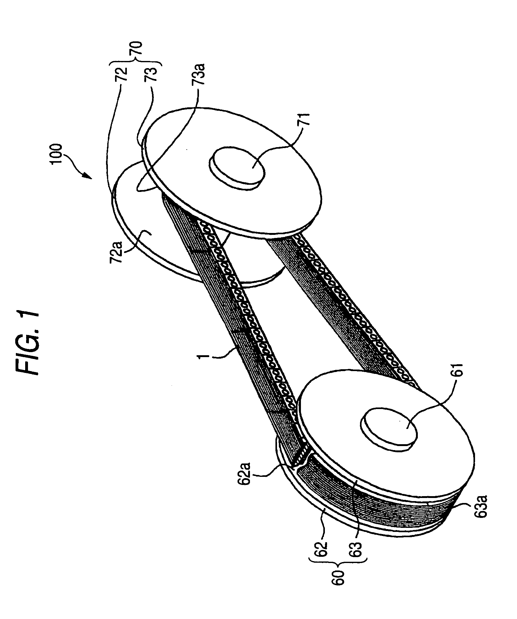
[0045]FIG. 1 is a perspective view schematically illustrating a configuration of a main part of a chain type continuously variable transmission (hereinafter, simply referred to as continuously variable transmission) serving as a power transmission apparatus including a power transmission chain according to one embodiment of the invention. As shown in FIG. 1, a continuously variable transmission 100 is mounted in a vehicle such as an automobile and includes a drive pulley 60 which serves as a first pulley and is made of metal (structural steel etc.), a driven pulley 70 which serves as a second pulley and is made of metal (structural steel etc.), and a continuous power transmission chain 1 (hereinafter, simply referred to as a chain) which are wound around both of the pulleys 60 and 70. Incidentally, FIG. 1 is a sectional view partially illustrating the chain 1 for an easy unde...


PUM

PropertyMeasurementUnit
Forceaaaaaaaaaa
Distanceaaaaaaaaaa
Tensionaaaaaaaaaa

Abstract

In the state where plural sheets of link plates which are single parts are laminated, tension for widening a distance between through-holes is loaded by a pair of pins which are inserted through the through-holes of the link plates so as to load pretension serving as a predetermined compressive residual stress on the link plates. Subsequently, the pair of pins are extracted from the link plates. Consequently, connection members are inserted through the corresponding through-holes of the plurality of link plates so as to assemble a chain with an endless shape.

Description

BACKGROUND OF THE INVENTION[0001]1. Field of the Invention[0002]The present invention relates to a method of manufacturing a power transmission chain and a pretension load device used in a manufacture of the power transmission chain.[0003]2. Related Art[0004]For example, a power transmission chain with an endless shape used in a power transmission apparatus such as a pulley type continuously variable transmission (CVT) etc. of an automobile includes a link unit which is constituted by a plurality of link plates laminated in a width direction of the chain and a pin which connects the link plates of the link unit to each other (for example, see JP-A-2006-102784). A power is transmitted when both end surfaces of the pin engage with a pair of sheave surfaces of the pulley.[0005]For example, as shown in JP-A-2006-102784, a strong tension to exceed a rated load is loaded on the power transmission chain during the manufacture so that a plastic deformation of the link plates occurs. Accordi...

Claims


Application Information

Patent Timeline
IPC IPC(8): B21L5/02B65G35/08
CPCB21L9/065C21D7/06B21L15/005B21L15/00
Inventor TADA, SEIJIMATSUMOTO, KOZUEROKKAKU, KAZUO
Owner JTEKT CORP
Why Eureka
Eureka Blog
Learn More