Image display apparatus with image entry function

a display apparatus and image technology, applied in the field of image display apparatuses, can solve the problems of reducing the aperture ratio of the pixel for display, increasing power consumption, and reducing the brightness of the screen, so as to suppress the decrease in the aperture ratio, reduce the power consumption of the backlight, and simplify the pixel structure

Inactive Publication Date: 2008-08-21
PANASONIC LIQUID CRYSTAL DISPLAY CO LTD +1
View PDF7 Cites 65 Cited by
  • Summary
  • Abstract
  • Description
  • Claims
  • Application Information

AI Technical Summary

Benefits of technology

[0018]According to the invention, since the data line and the storage line (or common line) are also used as the signal lines of the light sensor, the pixel structure is simplified, which can suppress a decrease in the aperture ratio of the pixel associated with the incorporation of the light sensor into the image display apparatus. Further, since light sensor signals are conveyed in the vertical (Y) and horizontal (X) directions, there is no need to perform region segmentation in the vertical (Y) direction to sequentially read out signals, and the information (address) of a two-dimensional touched position can be obtained based on the light sensor signals read in the vertical and horizontal directions.
[0019]Further, the suppression of a decrease in the aperture ratio can reduce an increase in the power consumption of the backlight associated with the incorporation of the light sensor into the image display apparatus, and the reduction of detection time can improve touch detection accuracy.

Problems solved by technology

The light sensor configuration disclosed in JP-A No. 2005-129948 requires a large number of elements including thin-film transistors in each pixel, which decreases the aperture ratio of the pixel for display and increases power consumption.
The decrease in the aperture ratio reduces the brightness of the screen, and the increase in power consumption reduces operating time particularly in a portable terminal.
Thus, the higher the resolution is, the slower the detection speed is.

Method used


Image

  • Image display apparatus with image entry function
  • Image display apparatus with image entry function
  • Image display apparatus with image entry function

Examples


first embodiment

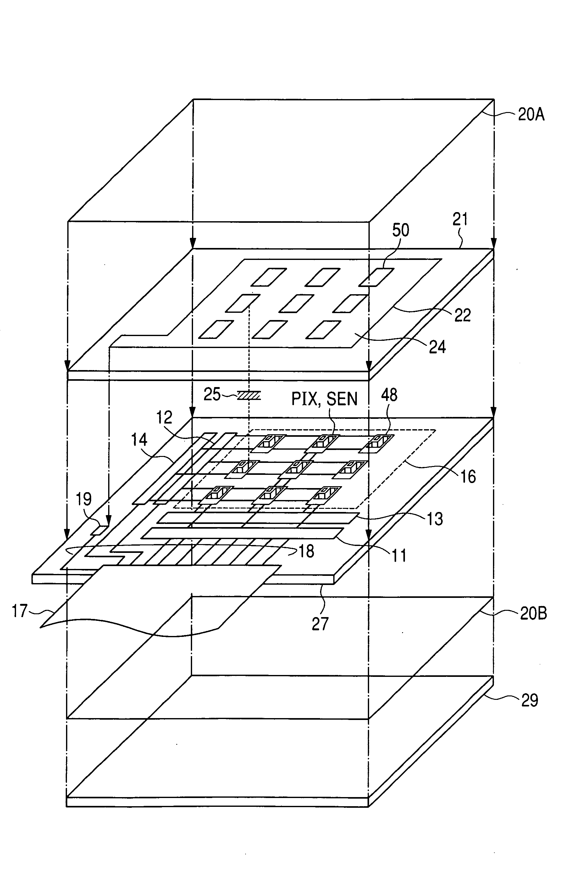
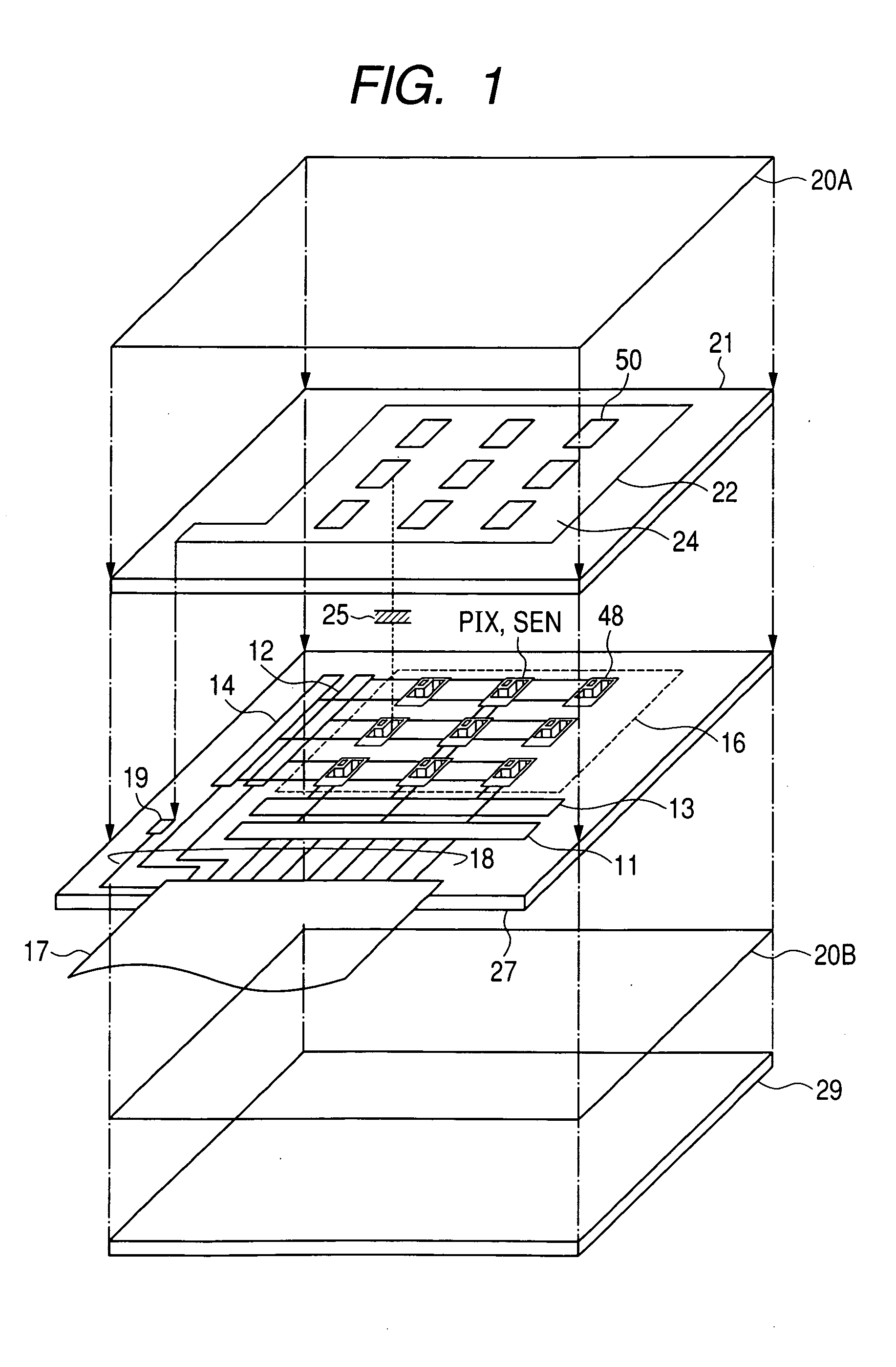
[0045]FIG. 1 is a developed perspective view of a liquid crystal display device with image entry function according to a first embodiment of the invention. In FIG. 1, there is a display area (pixel area) 16 in which a plurality of pixels (indicated by pixel electrodes 48) are matrix-arranged on the principal surface (inner surface on which thin-film transistors (TFT) etc. are formed) of a lower glass substrate 27 which is a first insulating substrate (TFT substrate). Pixels PIX which form the display area 16 have a light sensing function SEN as well as a display function. Further, there are, outside the pixel area 16 on the principal surface of the glass substrate 27, a data driver 11 connected to the source electrode or drain electrode (source electrode in this embodiment) of a switch TFT for pixel display (first thin-film transistor described later), a gate driver 12 which applies a selection signal to the gate electrode of a TFT for use as a pixel switch constituting a pixel, an ...

second embodiment

[0066]FIG. 8 is a circuit configuration diagram of the image display apparatus, according to a second embodiment of the invention. In the second embodiment, one pixel is composed of three RGB sub-pixels and a sensor circuit. In FIG. 8, for the convenience of description, pixels are arranged in two rows. A sub-pixel is composed of a switch TFT 60, a storage capacitor CST, and a liquid crystal capacitor CLC. The gate electrode of the switch TFT 60 is connected to a gate line VG(1). One end of the storage capacitor CST is connected to a storage line VST. This is the same configuration as the pixel circuit of an ordinary liquid crystal display device. The color filters of red, green, and blue are arranged in stripe shapes over the sub-pixels.

[0067]A horizontal sensor circuit SENX and a vertical sensor circuit SENY are disposed adjacent to the sub-pixel under the blue filter. These sensor circuits are composed of thin-film transistors (TFT). The drain (D) electrode of the horizontal sens...

third embodiment

[0071]FIG. 10 is a circuit configuration diagram of the image display apparatus, according to a third embodiment of the invention. The third embodiment differs from the second embodiment only in that switches 60X and 60Y composed of TFTs are connected between the respective source electrodes (S) of the horizontal sensor circuit SENX and the vertical sensor circuit SENY and the respective signal lines OUTX and OUTY. In the following, only the different point will be described. The gate electrode of the horizontal switch 60X connected to the horizontal sensor circuit SENX is connected to the gate line VG(1). The source electrode is connected to the signal line OUTX.

[0072]The gate electrode of the vertical switch 60Y connected to the vertical sensor circuit SENY is connected to the gate line VG(2). The source electrode (or drain electrode) is connected to the signal line OUTY. The light current of a sensor circuit selected by the gate line driving circuit is read out onto the signal li...


PUM


Abstract

An image display apparatus with image entry function of high accuracy enabling high-speed direct screen input without decreasing a pixel aperture ratio. Data lines of thin-film transistors which do not receive light and storage lines are connected to respective selector switches. The selector switches are turned on and off by a switching signal supplied through a switching line from a control circuit. The conveyance of a drive signal and a video signal supplied from a gate line driving circuit and a data line driving circuit and the conveyance of a light signal to an X address detection circuit and a Y address detection circuit are switched by turning on and off the selector switches.

Description

CLAIM OF PRIORITY[0001]The present application claims priority from Japanese application JP 2007-039272 filed on Feb. 20, 2007, the content of which is hereby incorporated by reference into this application.FIELD OF THE INVENTION[0002]The present invention relates to an image display apparatus incorporating an optical sensor in a display panel, and in particular, relates to an image display apparatus with image entry function of high speed and high accuracy enabling direct screen input without decreasing a pixel aperture ratio.BACKGROUND OF THE INVENTION[0003]An image display apparatus with image entry function in which information is inputted by a touch operation (hereinafter referred to simply as a touch) of a user's finger or the like on a screen is used in a touch-sensitive portable terminal such as a PDA and in a stationary customer guiding terminal such as an automatic reception machine. For the image display apparatus having such a screen touch input function, there are known...

Claims


Application Information

Patent Timeline
Patent Type & Authority Applications(United States)
IPC IPC(8): G06F3/041
CPCG06F3/042G06F3/0412
Inventor KINOSHITA, MASAYOSHIKAGEYAMA, HIROSHI
Owner PANASONIC LIQUID CRYSTAL DISPLAY CO LTD
Why Eureka
Try Eureka