

Liquid residual amount detection apparatus for liquid container
a liquid container and detection apparatus technology, applied in liquid/fluent solid measurement, instruments, machines/engines, etc., can solve the problems of large shape, complex mechanical switch mechanism, and high risk of damage to the liquid ejector head
- Summary
- Abstract
- Description
- Claims
- Application Information
AI Technical Summary
Benefits of technology
Problems solved by technology
Method used
Image

Examples
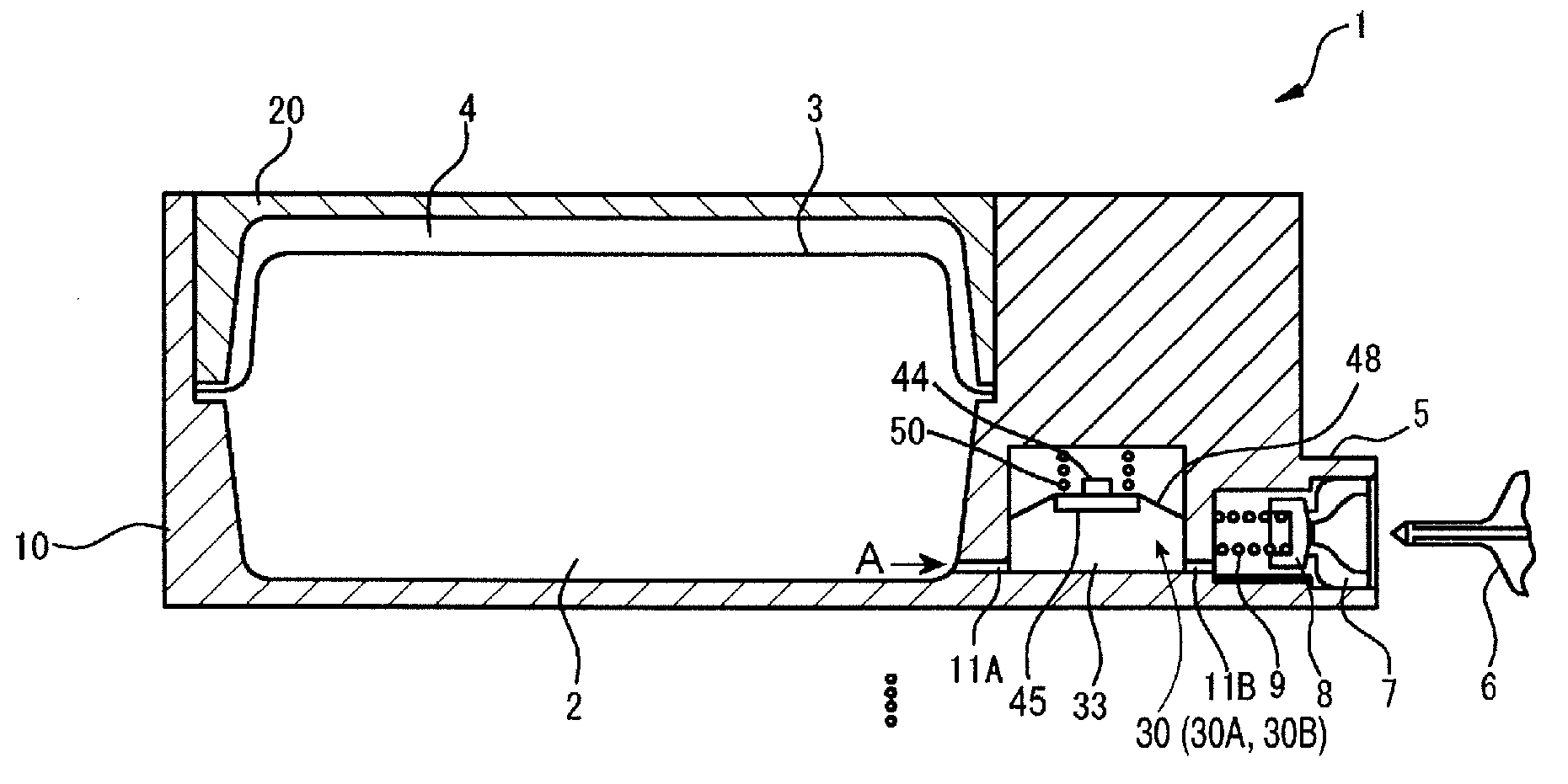
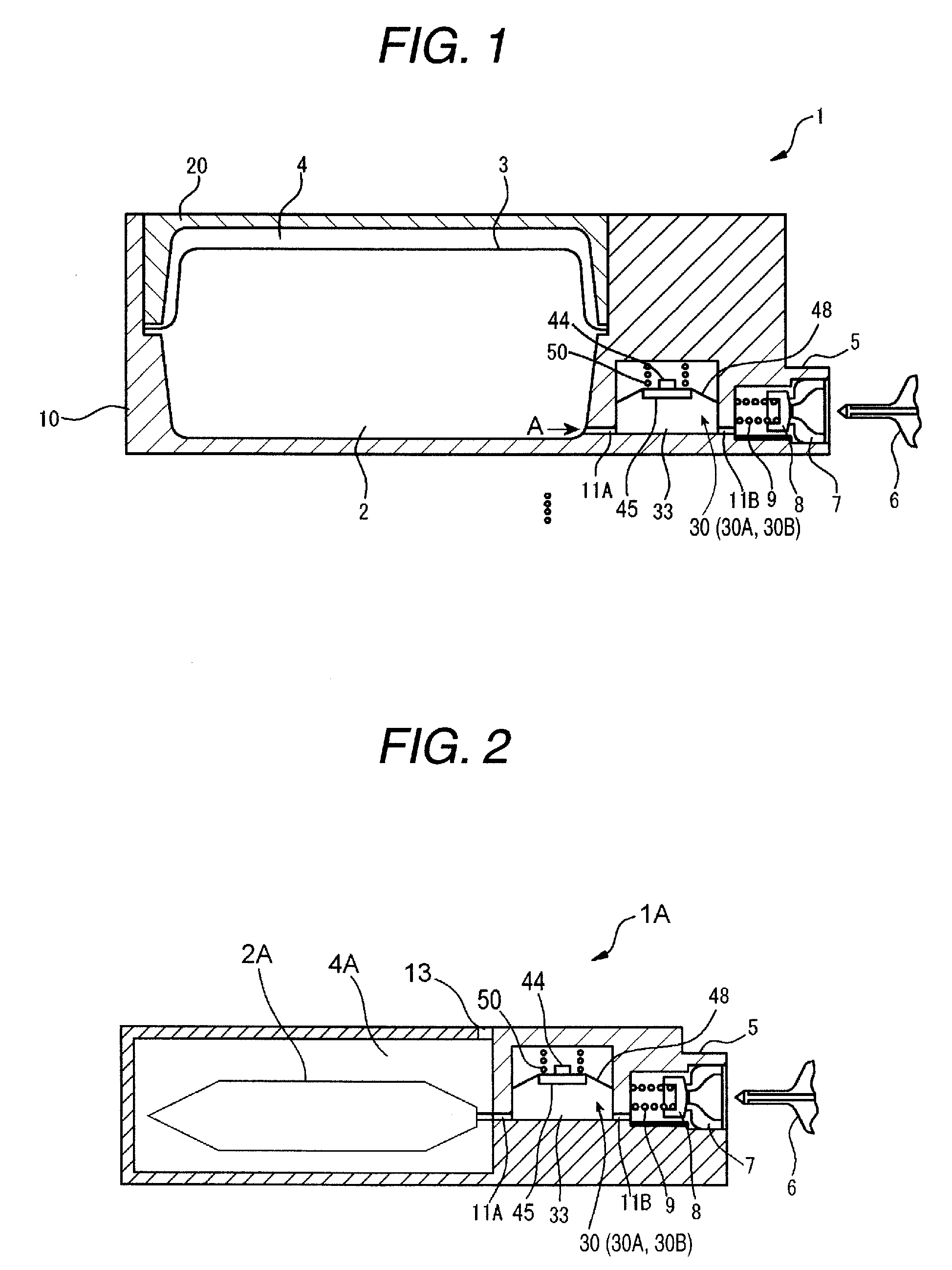
first embodiment
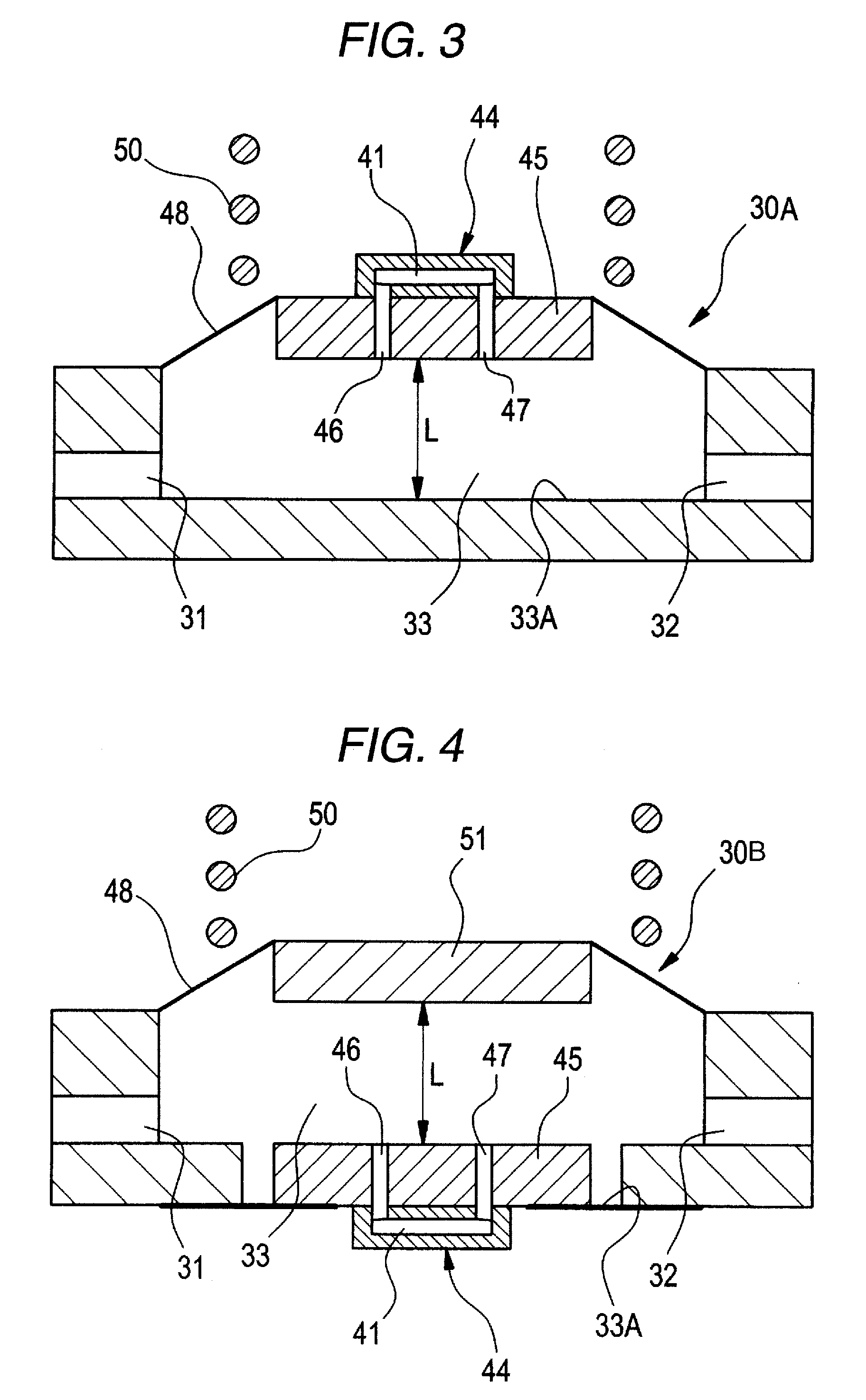
[0085]FIG. 3 is an enlarged cross-sectional view showing the structure of a liquid residual amount detection apparatus 30A according to the liquid residual amount detection apparatus 30 shown in FIG. 1 or 2. The liquid residual amount detection apparatus 30 has a cylindrical liquid detection chamber (sensor chamber) 33. The liquid detection chamber 33 has openings 31 and 32 in a bottom region. In a state where the connection to the recording apparatus is made, the opening 31 is connected to the liquid inlet port 11A that is connected to the liquid containing portion 2 (2A), and the opening 32 is connected to the liquid outlet port 11B that is connected to the liquid supply port 5. An upper portion of the liquid detection chamber 33 is partitioned by a diaphragm 48.
[0086]In this embodiment, the diaphragm 48 is formed of a flexible film member, and has an opening at its center. Further, a peripheral portion of the diaphragm 48 is fixed liquid-tight to an inner peripheral wall of the s...
second embodiment
[0093]In the second embodiment, the diaphragm 48 is formed of a flexible film member, and the peripheral portion thereof is fixed liquid-tight to the inner peripheral wall of the sensor chamber 33 at a predetermined height from the bottom of the sensor chamber. A pressure receiving plate 51 is fixed to an inner central portion of the diaphragm 48.
[0094]The support base 45 of the piezoelectric vibrating element 44 is fixed liquid-tight to the bottom inner surface 33A of the sensor chamber 33, and the piezoelectric vibrating element 44 is provided at the lower surface of the support base 45. The upper surface of the support base 45 is formed in parallel with the lower surface of the pressure receiving plate 51. In addition, like the first embodiment, a pair of areolar flow passages 46 and 47 are formed to pass through the support base 45 and to reach the vibrating plate of the piezoelectric vibrating element 44 from the sensor chamber 33.
[0095]The individual areolar flow passages 46 a...
third embodiment
[0109]FIG. 9 is a cross-sectional view showing a structure of a liquid residual amount detection apparatus 30C according to the invention of a liquid detection apparatus 30. The liquid residual amount detection apparatus 30C has a cylindrical liquid detection chamber 33. The liquid detection chamber 33 has openings 31 and 32 in a bottom region. In a state where the connection to the recording apparatus is made, the opening 31 is connected to the liquid inlet port 11A that is connected to the liquid containing portion 2, and the opening 32 is connected to the liquid outlet port 11B that is connected to the liquid supply port 5. In the liquid detection chamber 33, a piezoelectric sensor 34 is provided.
[0110]The piezoelectric sensor 34 has a sensor chip 40. The sensor chip 40 has a ceramic sensor main body 42 that has a sensor cavity 41 having a circular opening shape at its center, a vibrating plate 43 that is laminated on an upper surface of the sensor main body 42 so as to form an u...
PUM
 Abstract
Description
Claims
Application Information