

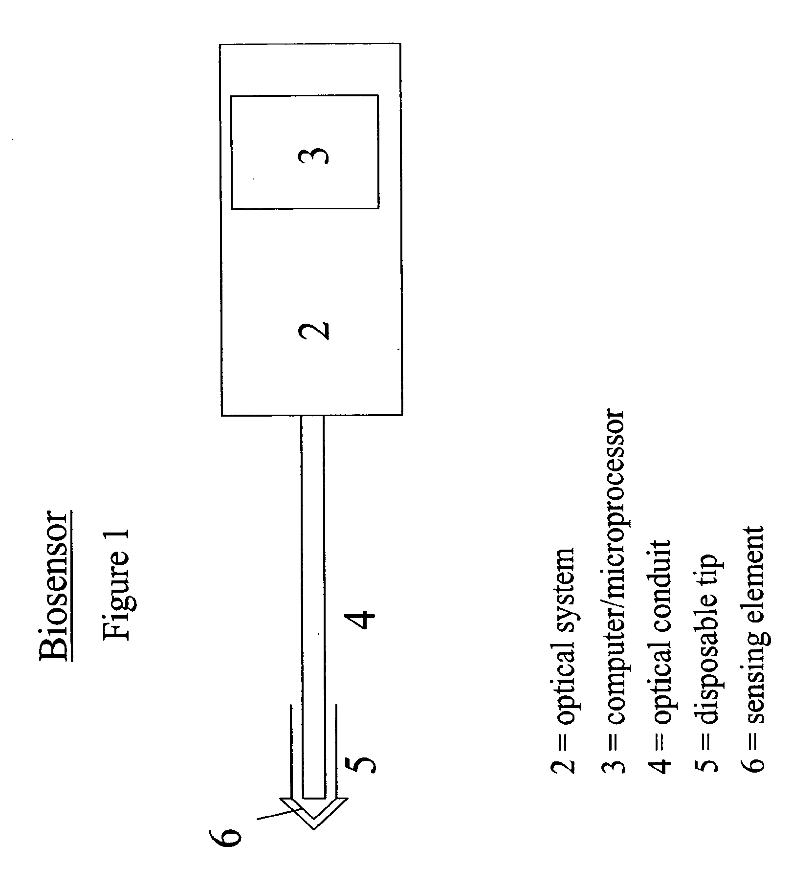
Fiber optic device for sensing analytes
a fiber optic device and analyte technology, applied in diagnostic recording/measuring, instruments, printers, etc., can solve the problems of slow progress in these approaches, sensor accuracy is affected, and patient compliance is problematic, etc., to achieve convenient use, convenient operation, and compact design and portability.
- Summary
- Abstract
- Description
- Claims
- Application Information
AI Technical Summary
Benefits of technology
Problems solved by technology
Method used
Image

Examples
example 1
[0053]According to one embodiment of the present invention, glucose galactose binding protein (GGBP) was used with a triple mutation including a cysteine substituted for an glutamic acid at position 149, an arginine substituted for an alanine at position 213 and a serine substituted for leucine at position 238 (E149C / A213R / L238S). The protein was labeled at the 149 position with N,N′-dimethyl-N-(iodoacetyl)-N′-(7-nitrobenz-2-oxa-1,3-diazol-4-yl)ethylenediamine (IANBD amide)oxy. This mutated GGBP (E149C / A213R / L238S) is specific for glucose, and the reporter group undergoes a fluorescence intensity change in response to glucose binding.
[0054]A multicoated or multilayer matrix was prepared as follows. A core matrix was formed by mixing 1 part dye-labeled binding protein (15 uM in PBS buffer, pH 7.4, prepared as described in PCT / US03 / 00203) with 2 to 4 parts 3 wt % alginate (v / v) in a scintillation vial and vortexing at slow speed. 3 mL of the resulting protein-alginate mixture was plac...
example 2
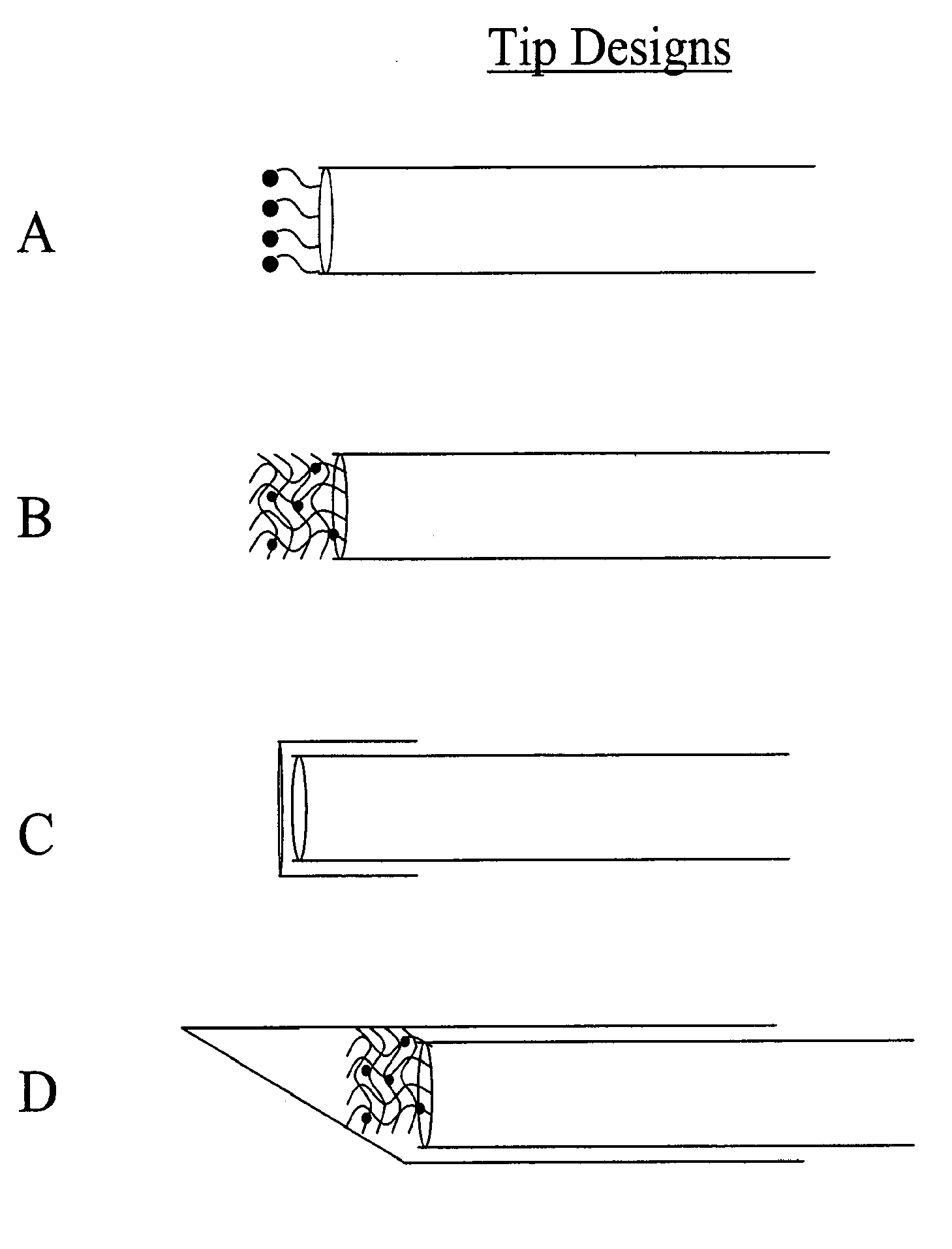
[0057]In another embodiment, the binding protein was glucose galactose binding protein (GGBP), with a cysteine substituted for an glutamic acid at position 149, an arginine substituted for an alanine at position 213 and a serine substituted for leucine at position 238 (E149C / A213R / L238S). The protein was labeled at the 149 position with N,N′-dimethyl-N-(iodoacetyl)-N′-(7-nitrobenz-2-oxa-1,3-diazol-4-yl)ethylenediamine (IANBD amide). The biosensor was prepared by inserting the tip of a 400 micron core diameter fiber into a short piece of catheter tubing, and allowing the catheter tubing to overhang the fiber tip by 0.1-1 mm. The fiber comprised a silica core, silica cladding, and polyimide buffer. The fiber diameter was 400 / 440 / 470 microns, where the slashes denote diameters measured from the core / cladding / buffer exteriors.
[0058]The immobilization matrix was a crosslinked alginate-based hydrogel, prepared by covalently crosslinking Pronova™ UP LVG alginate through the carboxyls with ...
example 3
[0062]In another embodiment of the present invention, a biosensor was formed by covalent attachment of a thin film to the surface of an optical fiber. The binding protein was glucose galactose binding protein (GGBP), with a cysteine substituted for a glutamic acid at position 149, an arginine substituted for an alanine at position 213 and a serine substituted for leucine at position 238 (E149C / A213R / L238S). The protein was labeled at the 149 position with N,N′-dimethyl-N-(iodoacetyl)-N′-(7-nitrobenz-2-oxa-1,3-diazol-4-yl)ethylenediamine (IANBD amide).
[0063]The biosensor was prepared by covalent attachment of an alginate matrix to the amine-functionalized surface of a silica fiber. The fiber comprised a silica core, silica cladding, and polyimide buffer. The fiber diameter was 400 / 440 / 470 microns, where the slashes denote diameters measured from the core / cladding / buffer exteriors.
[0064]The polyimide buffer was removed from the tip of the optical fiber by exposing the last few millime...
PUM
| Property | Measurement | Unit |
|---|---|---|
| length | aaaaa | aaaaa |
| length | aaaaa | aaaaa |
| pH | aaaaa | aaaaa |
Abstract
Description
Claims
Application Information