
Device for measuring size of steel bar in structure and method thereof

a technology of steel bars and structures, applied in the direction of material analysis using wave/particle radiation, x/gamma/cosmic radiation measuring, instruments, etc., can solve the problems of increasing difficulties and errors in examination, failure of detection using electromagnetic induction, and failure of stress wave examinations. , to achieve the effect of improving reliability and accuracy

Inactive Publication Date: 2008-08-21
NAT CENT UNIV
View PDF2 Cites 2 Cited by
  • Summary
  • Abstract
  • Description
  • Claims
  • Application Information

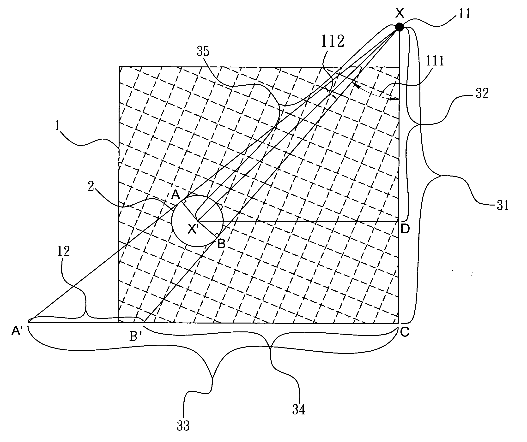
AI Technical Summary

Benefits of technology

[0006]Another purpose of the present invention is to compute the size of the steel bar with improved reliability and accuracy as a reference for a structure safety
[0007]To achieve the above purposes, the present invention is a device for measuring a size of a steel bar in a structure and a method thereof, comprising a radiation source, an imaging device and a computing module, where, through a gamma ray irradiated from the radiation source, a steel bar in a structure, whose position is obtained in advance, has its image projected on the imaging device; and a size of the steel bar is thus computed through geometric relationships between the image of the steel bar and the steel bar itself with improved reliability and accuracy as a reference for a structure safety. Accordingly, a novel device for measuring a size of a steel bar in a structure and a method thereof are obtained.

Problems solved by technology

However, a reinforced concrete structure having steel bar is an uneven composite material of steel bar, concrete, sand, aggregate, water and admixture, so that examinations done by using stress waves or through electromagnetism principles still face some difficulties.
Concerning examining steel bar in a structure, electromagnetism principles are usually used; yet their accuracies are so affected by permeability, conductivity, steel bar interval and steel bar construction that difficulties and errancies in examinations increase.
Yet, in places having multiple steel bars or jointing steel bar, interferences to electromagnetic induction occur with the neighboring steel bars and so detection using electromagnetic induction would fail.
Thus, a structure safety is not ensured.
Hence, the prior arts do not fulfill users' requests on actual use.

Method used


Image

  • Device for measuring size of steel bar in structure and method thereof
  • Device for measuring size of steel bar in structure and method thereof
  • Device for measuring size of steel bar in structure and method thereof

Examples


Embodiment Construction

[0010]The following description of the preferred embodiment is provided to understand the features and the structures of the present invention.

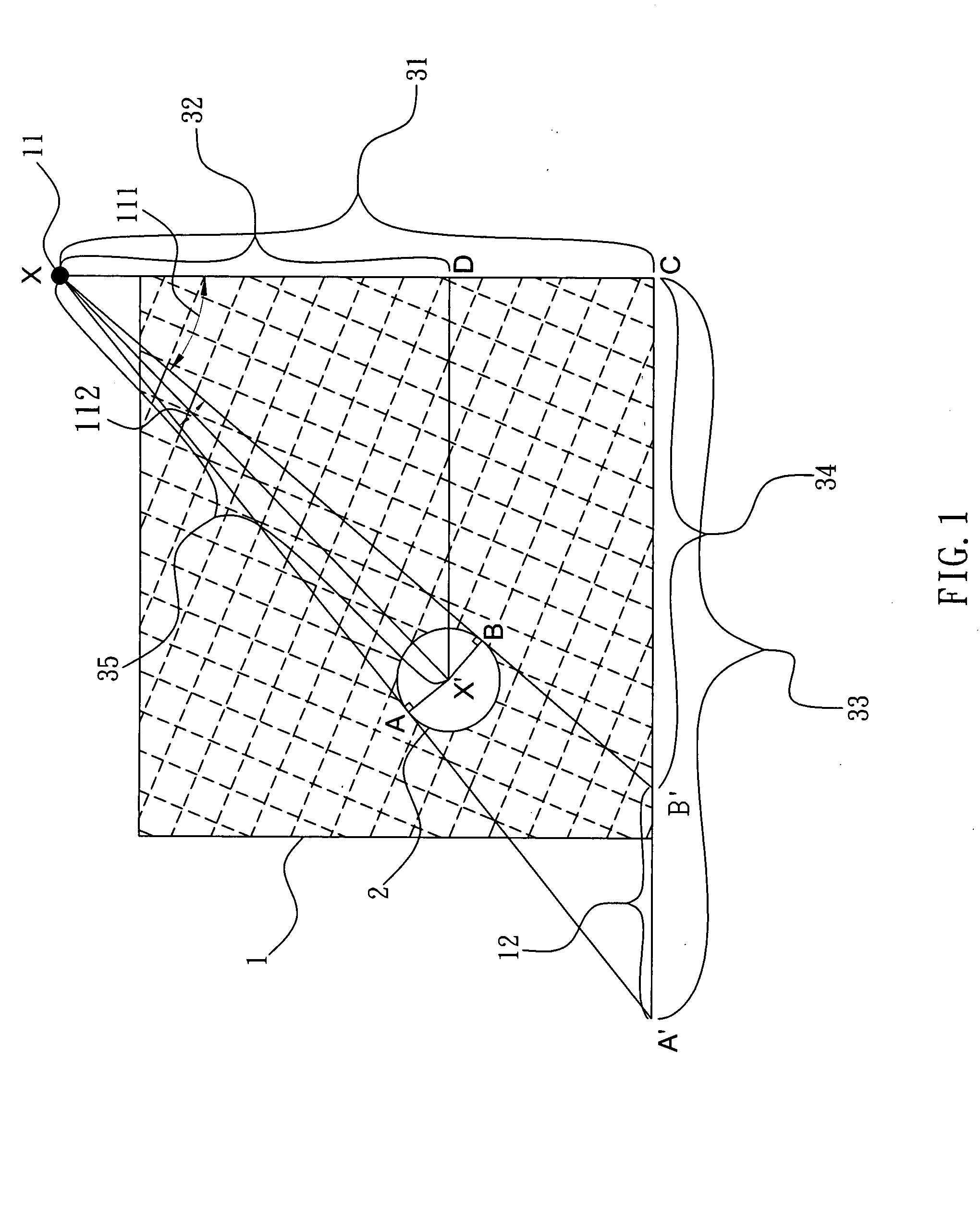
[0011]Please refer to FIG.1, which is a flow view showing a preferred embodiment according to the present invention. As shown in the figure, the present invention is a device for measuring a size of a steel bar in a structure and a method thereof. The device for measuring a size of a steel bar in a structure comprises a radiation source 11, an imaging device 12 and a computing module (not shown in the figure), where a size of a steel bar 2, whose position in a reinforced concrete structure 1 is acquired in advance, is computed with improved reliability and accuracy as a reference for a structure safety.

[0012]The radiation source 11 is located outside of the reinforced concrete structure and is a gamma ray, an X-ray or an ionizing radiation source The imaging device 12 is adhered to a horizontal surface of the reinforced concrete structure 1; ...


PUM

PropertyMeasurementUnit
sizeaaaaaaaaaa
angleaaaaaaaaaa
lengthaaaaaaaaaa

Abstract

A gamma ray, an X-ray or an ionizing irradiation penetrates through a steel bar in a reinforced concrete structure. An image of the steel bar is thus projected on a film. Through geometric relationships between the image and the steel bar itself, the size of the steel bar is calculated. The size of the steel bar obtained according to the present invention is reliable and accurate. And the data obtained can be used for structure safety.

Description

FIELD OF THE INVENTION [0001]The present invention relates to measuring a steel bar size; more particularly, relates to computing a size of a steel bar in a structure with improved reliability and accuracy as a reference for a structure safety.DESCRIPTION OF THE RELATED ARTS[0002]To obtain structure safety, examining steel bar in structure with reliability and accuracy is more and more important. However, a reinforced concrete structure having steel bar is an uneven composite material of steel bar, concrete, sand, aggregate, water and admixture, so that examinations done by using stress waves or through electromagnetism principles still face some difficulties.[0003]Concerning examining steel bar in a structure, electromagnetism principles are usually used; yet their accuracies are so affected by permeability, conductivity, steel bar interval and steel bar construction that difficulties and errancies in examinations increase.[0004]For example, a steel bar detector using eddy current ...

Claims


Application Information

Patent Timeline
Patent Type & Authority Applications(United States)
IPC IPC(8): G01N23/04
CPCG01B15/00E04C5/01
Inventor WANG, CHUNG-YUEPENG, PENG-CHING
Owner NAT CENT UNIV
Learn More