Loudspeaker enclosure with cylindrical compression chamber and tapered triangular folded horn terminating in an extended triangular bell.
Inactive Publication Date: 2008-08-21
WOELFEL JOSEPH DONALD
View PDF4 Cites 2 Cited by
Summary
Abstract
Description
Claims
Application Information
AI Technical Summary
This helps you quickly interpret patents by identifying the three key elements:
Problems solved by technology
Method used
Benefits of technology
[0027]This loudspeaker is a single-driver design, in which the rear of the cone is coupled to an expanding triangular column of air which is coupled to the air in the listening room through an extended triangular bell. As in all
Problems solved by technology
Despite a hundred plus years of research, the variables which explain listener satisfaction with loudspeakers are not completely understood.
Two, three and four way systems, with crossover networks, are often reported to improve the accuracy of the sound, but reduce the immediacy and reality.
Careful engineering can overcome or at least ameliorate these difficulties, but corrections for these effects are often expensive, and highly rated full range multi-way speaker systems tend to be extraordinarily expensive.
Transmission line, acoustical labyrinth and similar designs control the back wave of loudspeakers,
Method used
Image
Click on the blue label to locate the original text in one second.
Reading with bidirectional positioning of images and text.
Examples
Example
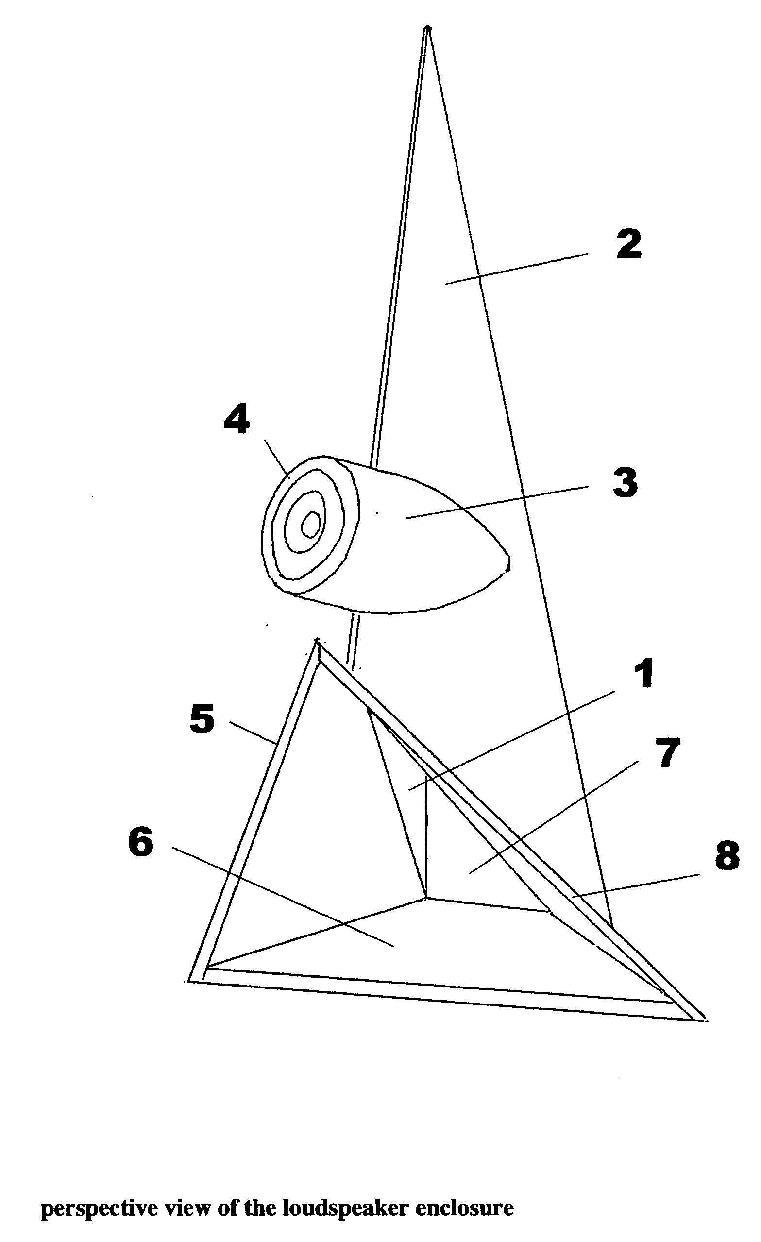
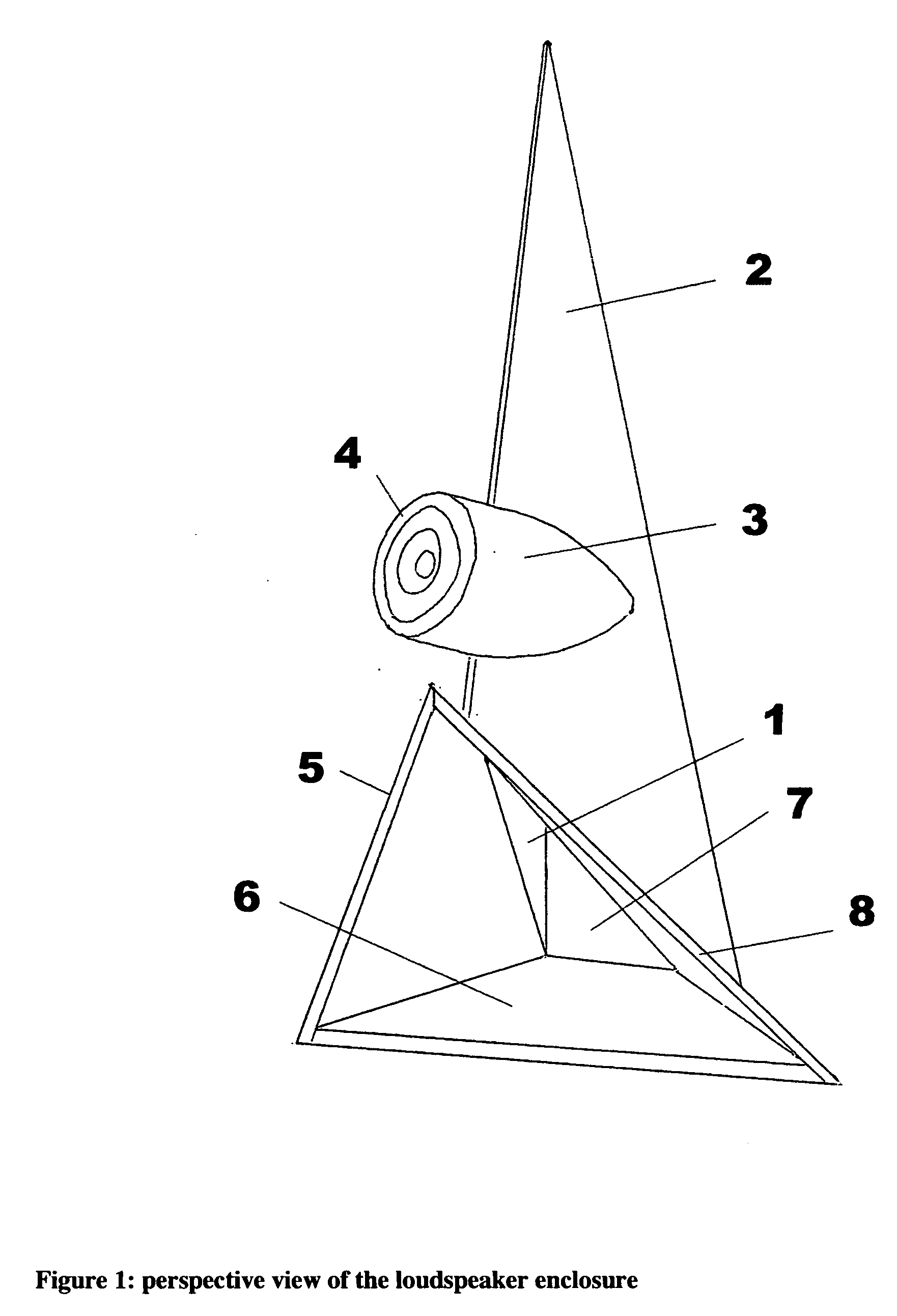
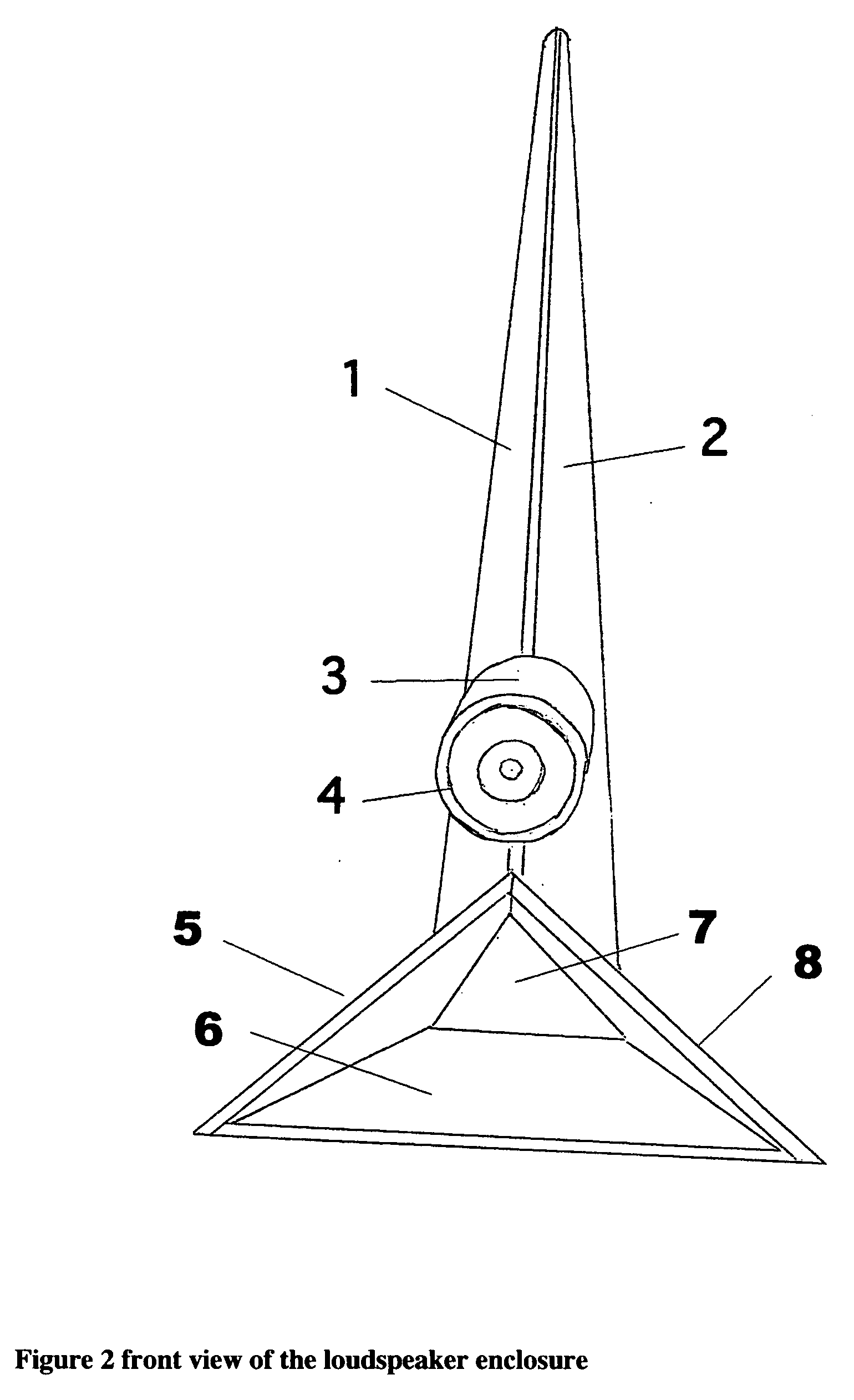
[0042]The loudspeaker enclosure which comprises the invention, herein also referred to as the enclosure, consists of a compression cylinder 3, and a front speaker baffle 4 to which a loudspeaker is mounted. The compression cylinder 3 is notched at the rear to fit securely to the hom, consisting of a left horn side 1, a right horn side 2 and a horn back 7. The horn is attached to an extended bell consisting of the bell left side 5, the bell bottom 6, and the bell right side 8.
[0043]FIG. 4, a cutaway side view of the enclosure, shows the interior baffling consisting of a baffle, 9, and a baffle end plug 10.
[0044]The rear sound wave of the speaker is compressed in the compression cylinder 3, and enters the horn through the notch 11 cut into the front of the horn. It is directed by the interior baffling upward to the apex of the horn, then downward to exit the horn into the bell, then exits the bell into the room.
[0045]While most rear-loaded loudspeaker enclosures are generally classifi...
PUM
Abstract
A loudspeaker enclosure with a cylindrical compression chamber to which an electro-dynamic loudspeaker is mounted at the front. The rear of the cylindrical compression chamber is faired to the front of a tapered triangular pipe with a slot to connect the air column in the cylinder to the air column in the triangular tapered pipe. A baffle inside the tapered triangular pipe splits the tapered pipe into two triangular pipes, effectively increasing the length of the triangular air column substantially. This tapered triangular air column expands into an extended triangular bell and then the room.
Description
REFERENCES CITED[0001]1,407,574Feb. 21, 1922Price1988250Jan. 15, 1935Olson6,625,291Sep. 23, 2003Mohler6,571,909Jun. 3, 2003Olinger5,123,500Jun. 23, 1992Malhoit4,558,762Dec. 17, 1985Carlsson2,224,919Dec. 7, 1940Olson2310243Feb. 9, 1943Klipsch4,249,037Feb. 3, 1981Dexter1,477,554Dec. 18, 1923Grissinger6,425,456Jul. 30, 2002George2401328Jun. 4, 1946Ruber, Black6,675,932Jan. 13, 2004Manrique, Wathen6,385,324May 7, 2002Koppen, Koppen5,866,858Feb. 2, 1999Dewey4819,716Apr. 11, 1989Dick4,750,585Jun. 14, 1988Collings[0002]Other references:[0003]Olson, Harry M., Music, Physics and Engineering, Dover, 1967, (Revised Edition) pp. 96-97.[0004]Woelfel, J., and N. J. Stoyanoff, (1995) CATPAC: A neural network for qualitative analysis of text, in Woelfel, J., and N. J. Stoyanoff, (1995). Artificial Neural Networks for Advertising and Marketing Research, Amherst, N.Y., RAH Press, pp. 51-70.BACKGROUND[0005]Despite a hundred plus years of research, the variables which explain listener satisfaction with...
Claims
Application Information
Patent Timeline
Application Date:The date an application was filed.
Publication Date:The date a patent or application was officially published.
First Publication Date:The earliest publication date of a patent with the same application number.
Issue Date:Publication date of the patent grant document.
PCT Entry Date:The Entry date of PCT National Phase.
Estimated Expiry Date:The statutory expiry date of a patent right according to the Patent Law, and it is the longest term of protection that the patent right can achieve without the termination of the patent right due to other reasons(Term extension factor has been taken into account ).
Invalid Date:Actual expiry date is based on effective date or publication date of legal transaction data of invalid patent.