Wheel Support Bearing Assembly

Inactive Publication Date: 2008-08-21
NTN CORP
View PDF5 Cites 14 Cited by
  • Summary
  • Abstract
  • Description
  • Claims
  • Application Information

AI Technical Summary

Benefits of technology

[0005]An object of the present invention is to provide a wheel support bearing assembly, in which exposure of a sliding surface for outboard sealing lips to the mud

Problems solved by technology

This in turn results in increase of an axial length of the be

Method used


Image

  • Wheel Support Bearing Assembly
  • Wheel Support Bearing Assembly
  • Wheel Support Bearing Assembly

Examples


third embodiment

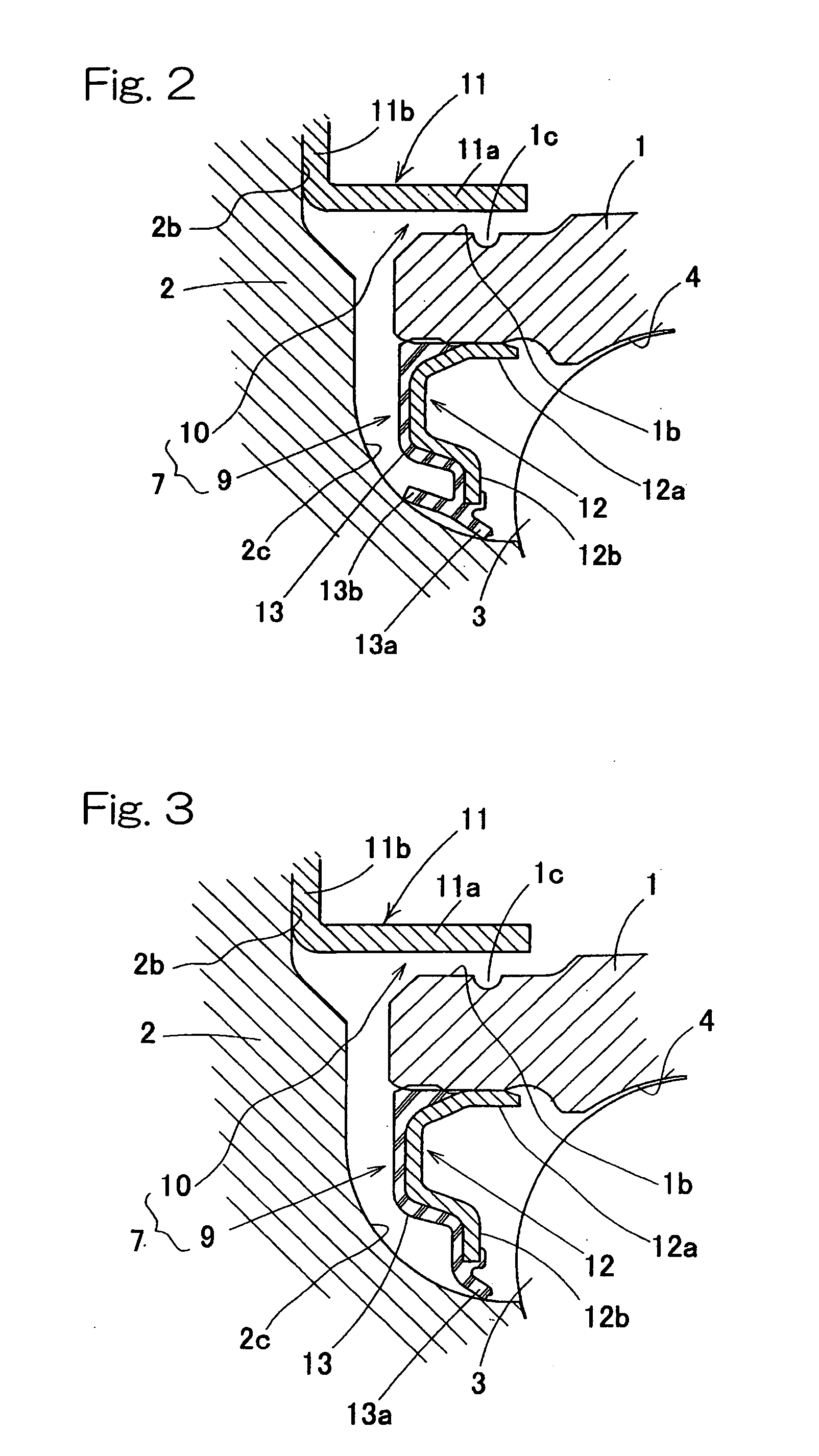
[0039]FIG. 5 illustrates a third preferred embodiment of the present invention. The core metal 12 of the generally L-sectioned configuration forming the contact seal 9 is fixed in position on the outer member 1 by mounting the cylindrical wall 12a onto the outer peripheral surface 1b of the outer member 1 from the outboard side. A gap between an outer peripheral surface of this cylindrical wall 12a and the inner peripheral surface of the shielding plate 11 is rendered to be a labyrinth seal 10. In this third embodiment, an inboard end 1e of the cylindrical wall 12a as one component part of the contact seal 9 functions as a guide structure. Water flowing in between the shielding plate 11 and the outer member 1 along the flange 2a and shielding plate 11 and water flowing in between the shielding plate 11 and the outer member 1 along the outer peripheral surface of the outer member 1 can be dammed by the inboard end 1c and can be guided in a direction downwardly of the outer member 1 s...

first embodiment

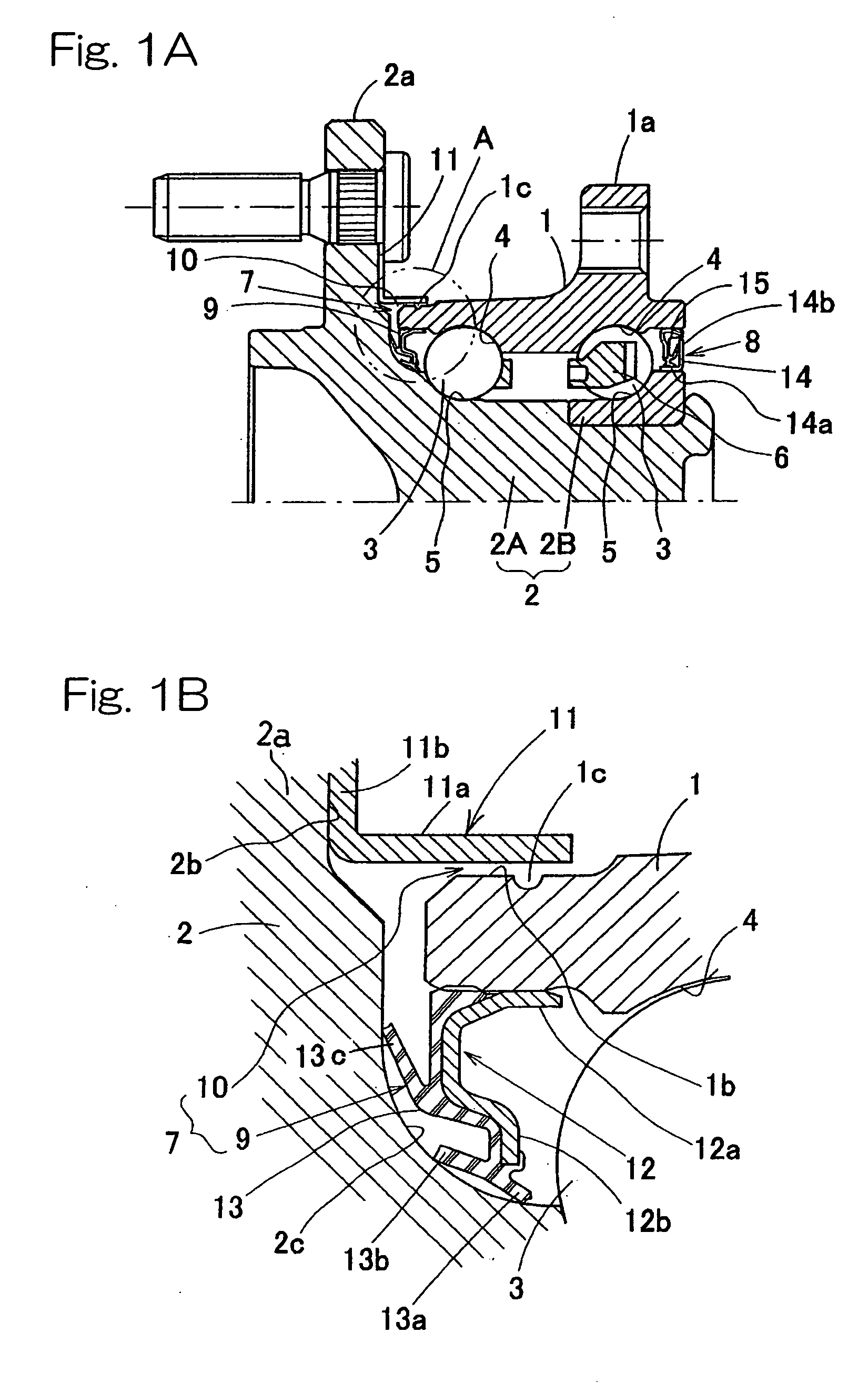
[0041]FIG. 6 illustrates a fourth preferred embodiment of the present invention. In the first embodiment shown in FIG. 1, the tubular wall 11a of the shielding plate 11 in the outboard sealing structure 7 is so shaped as to have a water return for returning water, flowing along an outer surface of the shielding plate 11, towards a base end of the tubular wall 11a (a corner area 11c between the tubular wall 11a and the upright wall 11b). More specifically, by selecting an angle α between the tubular wall 11a and the upright wall 11b to be of a value smaller than 90°, the tubular wall 11a is formed to have a tapered shape with the diameter of a free end thereof greater than that of the base end 11c to define the water return. In the case of this construction, the gap of the labyrinth seal 10 flares towards the inboard side, but water flowing along the inboard surface 2b of the wheel mounting flange 2b and the upright wall 11b or water flowing along the outer peripheral surface of the ...


PUM


Abstract

Sealing structures (7, 8) are installed to seal opposite open ends of an annular bearing space between an outer member (1) and an inner member (2). A wheel mounting flange (2a) of the inner member (2) is provided with a shielding plate (11). The shielding plate (11) has a tubular wall (11a) forming a labyrinth seal (10) in the vicinity of an outer peripheral surface (1b) of an outboard end of the outer member (1). The outer peripheral surface (1b) is provided with a guide structure (1c) for guiding downwardly water, flowing in between the shielding plate (11) and the outer member (1) along the flange (2a) and the shielding plate (11), and water flowing in between the shielding plate (11) and the outer member (1) along the outer peripheral surface of the outer member (1). The guide structure (1c) is constituted by an annular groove or projection.

Description

FIELD OF THE INVENTION[0001]The present invention generally relates to a wheel support bearing assembly for use in automotive vehicles and, more particularly, to a sealing structure employed in such wheel support bearing assembly.BACKGROUND ART[0002]Considering that most bearing assemblies used in vehicles, for example, cars are generally operated under severe conditions exposed to road surfaces, the bearing assemblies are generally required to have a reliable sealing structure to protect them from external dusts and dirt and muddy water. Also, with a view to eliminating the necessity of maintenance, a high effect of preventing leakage of a grease filled in the bearing assembly is also required. For these reasons, such a sealing structure as shown in FIG. 9A has long been employed. (See, for example, the Japanese Laid-open Patent Publication No. 2003-202028.) The bearing assembly shown therein includes an outer member 31 having double rows of raceway surfaces 34, an inner member 32 ...

Claims


Application Information

Patent Timeline
IPC IPC(8): F16C33/80F16C19/18B60B35/18F16C33/60F16C33/76F16C33/78
CPCF16C19/186F16C33/58F16C2326/02F16C33/7886F16C33/805F16C33/7876F16C33/586
Inventor TORII, AKIRAISHIKAWA, TOMOMISUZUKI, SYOUGO
Owner NTN CORP
Why Eureka
Try Eureka