Displaying anatomical patient structures in a region of interest of an image detection apparatus

a technology of image detection apparatus and anatomical patient, which is applied in the field of displaying anatomical patient structure in a region of interest of movable image detection apparatus, can solve the problems of slow image response time, complicated handling, and interruption of patient observation, and achieves the effects of reducing the area of interest, good image quality, and fast frame ra

Inactive Publication Date: 2008-08-21
BRAINLAB
View PDF9 Cites 25 Cited by
  • Summary
  • Abstract
  • Description
  • Claims
  • Application Information

AI Technical Summary

Benefits of technology

[0010]A method in accordance with the present invention optimizes the display of an anatomical patient structure in a region of interest of a movable image detection apparatus. When the image detection apparatus is moved, the region of interest is shifted to detect particular prope

Problems solved by technology

In doing so, the observation of the patient may be interrupted and the handling may be complicated.
This approach, however, has a disadvantage of slow image response time.
When the regions o

Method used


Image

  • Displaying anatomical patient structures in a region of interest of an image detection apparatus
  • Displaying anatomical patient structures in a region of interest of an image detection apparatus
  • Displaying anatomical patient structures in a region of interest of an image detection apparatus

Examples


Embodiment Construction

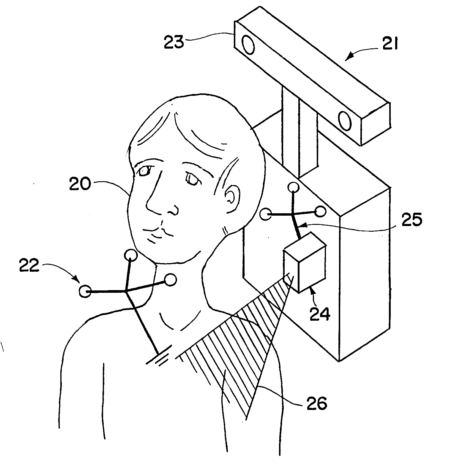
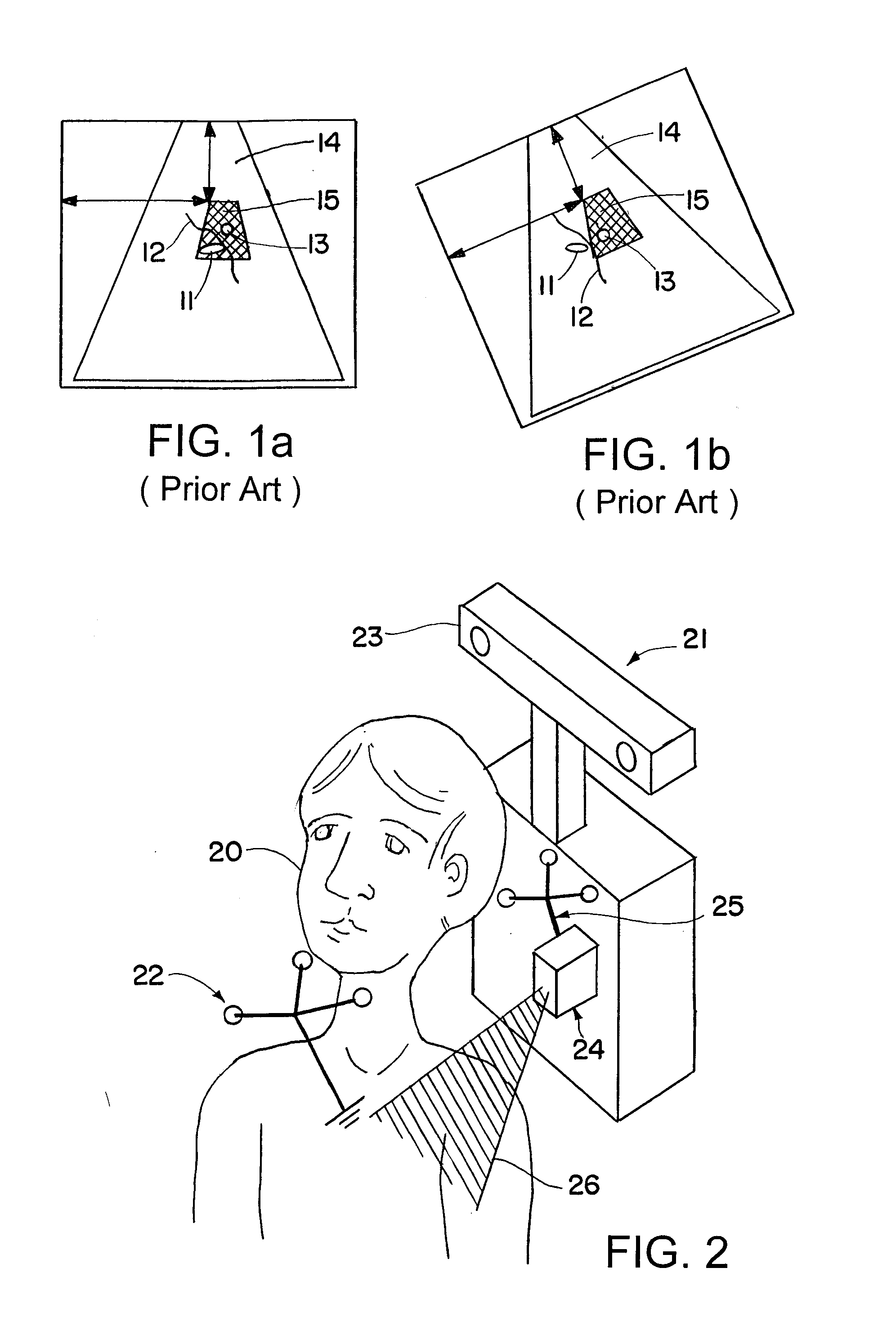
[0031]Image-guided surgery or treatment often relies upon a navigation system to track the patient and various medical instruments to provide useful information to the physician. In an example embodiment shown in FIG. 2, an ultrasound device is used in connection with the navigation system to perform so-called “navigated ultrasound integration.” In such a procedure, a patient 20 is “registered” so that a navigation system 21“knows” the patient's position and, when the patient 20 has a reference array 22 attached, the navigation system 21 can track the patient's movement using a sensor array 23. In the present example, an ultrasound device 24 is equipped with a reference array 25 so that the navigation system 21 can detect the ultrasound device's position and can track its movement. Like the patient 20 the ultrasound device 24 may be registered or “calibrated” such that the navigation system 21 knows the position of the ultrasound device's image detection plane 26 relative to the ref...


PUM


Abstract

A method and device for detecting and displaying an anatomical patient structure in a region of interest of a movable image detection apparatus such as an ultrasound probe. After the region of interest is defined in a patient coordinate system, movement of the image detection apparatus can be tracked, and the position of the region of interest can be changed or shifted to compensate for the movement of the image detection apparatus.

Description

RELATED APPLICATION DATA [0001]This application claims priority of U.S. Provisional Application No. 60 / 891,787 filed on Feb. 27, 2007, and EP 07003209 filed on Feb. 15, 2007, which are incorporated herein by reference in their entirety.FIELD OF THE INVENTION [0002]The present invention relates to a method and system for displaying an anatomical patient structure in a region of interest of a movable image detection apparatus.BACKGROUND OF THE INVENTION [0003]Ultrasound Doppler flow images are normally shown in a rather small part of a standard B-mode ultrasound image. The user can define a region of interest (ROI) relative to the image coordinates, i.e., relative to a coordinate system of an ultrasound head, wherein flow information is displayed, color-coded, in this region. The region of interest is a region in which an image detection device can detect particular properties of the patient structure.[0004]When the ultrasound probe (head) is moved, the region of interest maintains it...

Claims


Application Information

Patent Timeline
IPC IPC(8): A61B8/00
CPCA61B8/06G06T2207/30104A61B8/469A61B19/52A61B19/5244A61B2019/5255A61B2019/5265A61B2019/5276A61B2019/5291G01S7/52063G01S7/52066G01S15/8936G06T7/0042G06T2207/10132G06T2207/20104A61B8/13A61B8/4245A61B34/20A61B90/36A61B2034/2055A61B2034/2065A61B2090/365A61B2090/378G06T7/73
Inventor LEIDEL, MARTINVOLLMER, FRITZTHEIMANN, INGMAR
Owner BRAINLAB
Why Eureka
Try Eureka