Method and system using MRI compatibility defibrillation pads

a defibrillator and compatibility technology, applied in the field of defibrillator systems, can solve the problems of eddy currents that could interfere with imaging signals, create image artifacts, and cannot be operationally practical to couple patients to the defibrillator, so as to eliminate time delays and minimize image artifacts

Inactive Publication Date: 2008-08-21
GENERAL ELECTRIC CO
View PDF6 Cites 38 Cited by
  • Summary
  • Abstract
  • Description
  • Claims
  • Application Information

AI Technical Summary

Benefits of technology

[0005]The present technique provides a defibrillation system based upon defibrillation pads couplable to a patient while the patient undergoes a medical procedure. In accordance with embodiments of the present technique, the defibrillation pads are operable within an imaging device such as an MRI device. Accordingly, the provided defibrillation pads and components thereof are configured to minimally interfere with electromagnetic signals produced by the MRI device. In this manner, image artifacts are minimized to the extent the images can provide desirable information relating to the patient to a clinician. Further, the present technique enables use of the defibrillation pads within the patient volume of the MRI device, thus eliminating time delays otherwise incurred in situations requiring exiting the patient from the MRI system before defibrillation pads can be applied to the patient.

Problems solved by technology

However, there are instances where the defibrillator pads can interfere with the medical procedure, such that it may not be operationally practical to couple the patient to the defibrillator.
Electromagnetic interactions of the gradient and RF magnetic fields with various components of the defibrillation pads, e.g., wire leads and electrodes, may induce eddy currents that could interfere with imaging signals producing patient image data.
To the extent such interference effects are present during the imaging procedure, they may create image artifacts and degrade image quality.
Without a means to preserve image quality in the presence of defibrillation pads, it could become unfeasible to place such pads in the proximity of the MR imaging coils and expedite delivery of therapy in the event of urgent medical need.

Method used


Image

  • Method and system using MRI compatibility defibrillation pads
  • Method and system using MRI compatibility defibrillation pads
  • Method and system using MRI compatibility defibrillation pads

Examples


Embodiment Construction

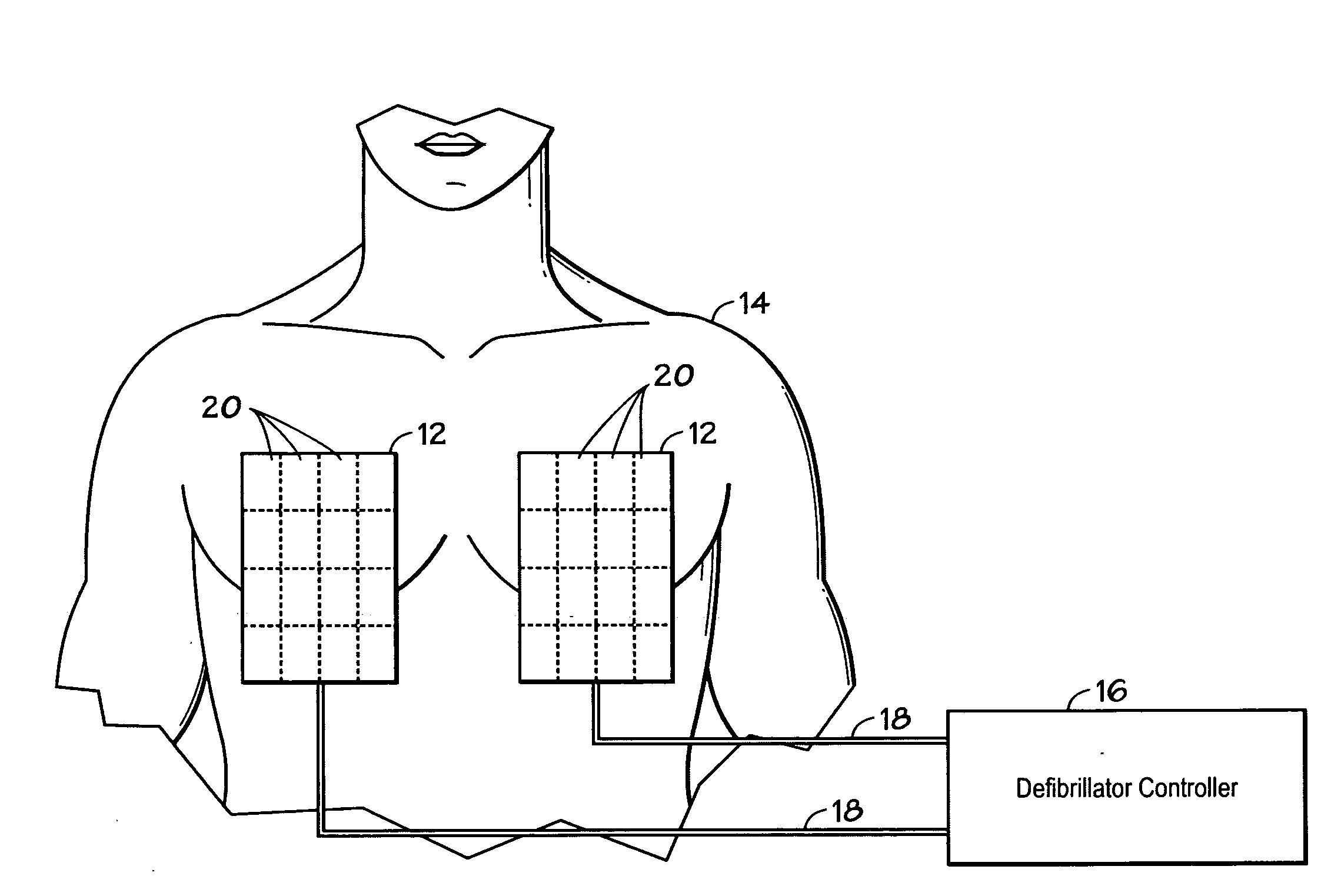
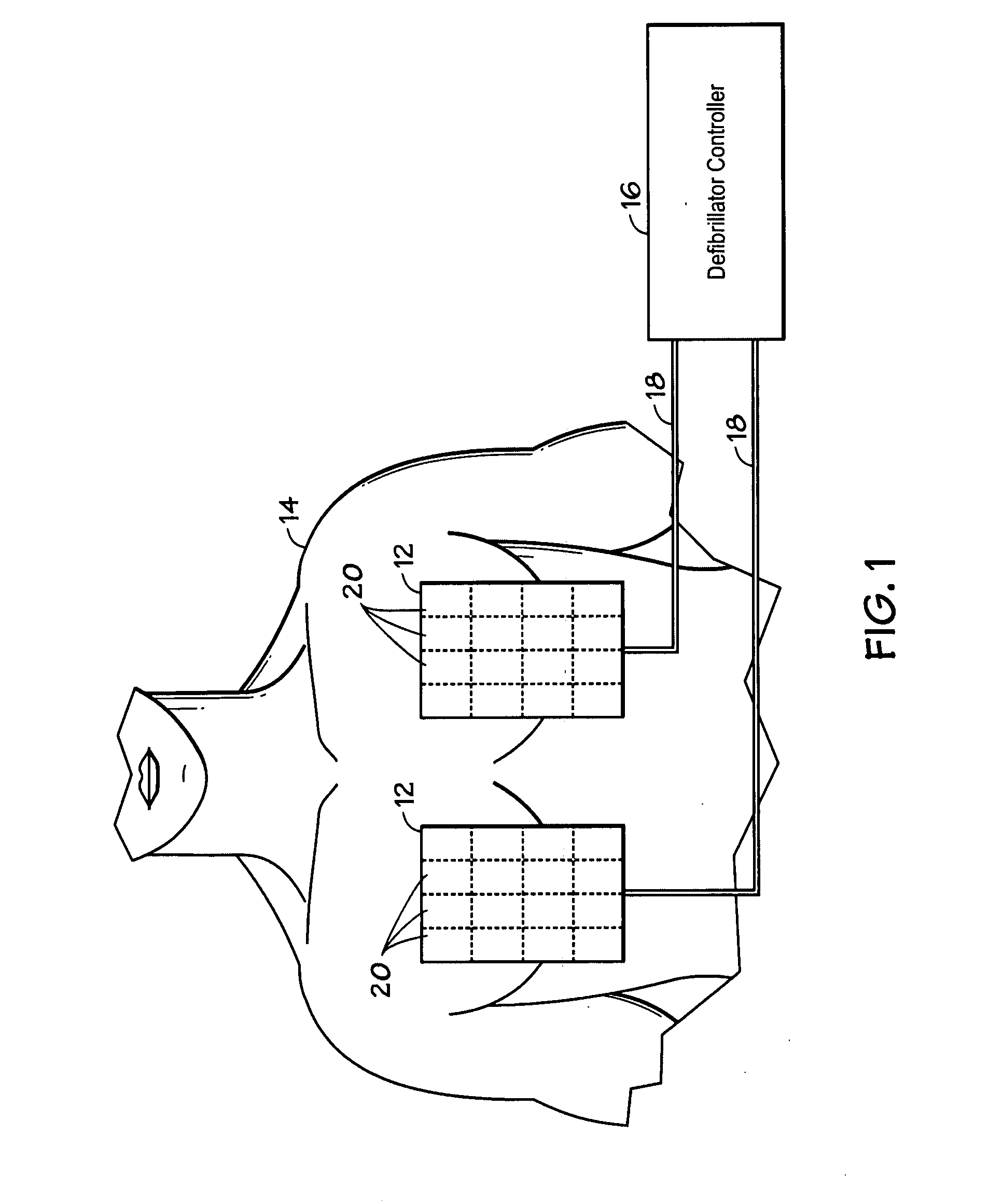
[0013]Turning now to the drawings and referring to FIG. 1, two defibrillation pads 12 disposed on a chest area of a patient 14 are shown, in accordance with an embodiment of the present technique. Each of defibrillation pads 12 are generally couplabe to a defibrillation control system 16 via wire lead 18. Defibrillation control system 16 may be a generic defibrillation system having connections compatible with multiple types and / or brands of defibrillation pads, such defibrillation pads 12. While the present embodiment illustrates two defibrillation pads coupled to control system 16, other embodiments may include more than two defibrillation pads, such as defibrillation pads 12, coupled to control system 16. Defibrillation pads 12 may be coupled to defibrillation control system 16 using plugs, clips, caps and so forth. Such coupling devices enable delivery of voltages and currents, such as those desired during defibrillation treatments, to and from pads 12. While in the illustrated ...


PUM


Abstract

In accordance with embodiments of the present technique an electrode pad for medical use is provides. The electrode pad comprises a support layer a plurality of electrodes mounted on the support layer and electrically insulated from one another, and a plurality of leads electrically coupled to the electrodes for selectively placing the electrodes at a desired electrical potential.

Description

BACKGROUND[0001]The present invention relates generally to defibrillation systems. Particularly, the invention relates to defibrillation pads operable in conjunction with other medical systems during various medical procedures.[0002]Defibrillation devices, otherwise known as defibrillators, are used to correct a medical condition known as fibrillation, which is a very rapid, disorganized twitching or trembling of the heart muscle in place of a normal rhythmic beat. To correct such a condition, a defibrillator directs a pulse of electrical direct-current (DC) into the heart to return it to its regular rhythm. To deliver such a pulse of electrical current to the heart of a patient, two defibrillation pads are attached, typically on the chest area of the patient. An electrical voltage applied between the defibrillation pads induces current through the heart of the patient, restoring the normal rhythm of the heart. Defibrillation pads are typically spread out in two dimensions, with typ...

Claims


Application Information

Patent Timeline
Patent Type & Authority Applications(United States)
IPC IPC(8): A61N1/05
CPCA61N1/046A61N1/0476G01R33/28A61N2001/086A61N1/0492A61N1/086
Inventor MALLOZZI, RICHARD PHILIPDUMOULIN, CHARLES LUCIAN
Owner GENERAL ELECTRIC CO
Why Eureka
Try Eureka