Photoelectric millimeter wave searching and tracking device and method

A tracking device and millimeter-wave technology, applied in measuring devices, radio wave measurement systems, radio wave reflection/re-radiation, etc., can solve the problems of no target distance measurement, no target threat judgment, small laser beam divergence angle, etc.

Active Publication Date: 2018-05-08
中国人民解放军92232部队 +1
View PDF5 Cites 9 Cited by
  • Summary
  • Abstract
  • Description
  • Claims
  • Application Information

AI Technical Summary

Problems solved by technology

However, limited by the energy of the laser pulse emitted by the laser rangefinder laser, in order to achieve distance measurement of small-sized targets at a relatively long distance, the laser beam divergence angle is generally small. Therefore, the laser rangefinder can only be used in photoelectric detection equipment. Used when accurately tracking the target: the target must be tracked stably so that it is precisely in the center of the field of view of the photoelectric detection device
However, when photoelectric detection equipment is used to search for large-scale targets, because the target can randomly appear in any position in the field of view of the photoelectric detection equipment, it is difficult to obtain the distance of the target by using the laser range finder when the photoelectric detection equipment is searching. When detecting "low, small and slow" targets, due to the lack of target distance value, it is impossible to judge the threat of the target, so that the search efficiency of photoelectric detection equipment is greatly reduced
[0011] To sum up, compared with active radar and millimeter wave, photoelectric detection equipment is more suitable for searching "low, small and slow" targets in complex backgrounds, but the disadvantage is that there is no target distance measurement

Method used


Image

  • Photoelectric millimeter wave searching and tracking device and method
  • Photoelectric millimeter wave searching and tracking device and method
  • Photoelectric millimeter wave searching and tracking device and method

Examples


Embodiment Construction

[0082] The present invention will be described in further detail below in conjunction with the accompanying drawings and specific embodiments.

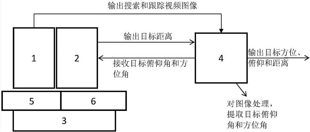
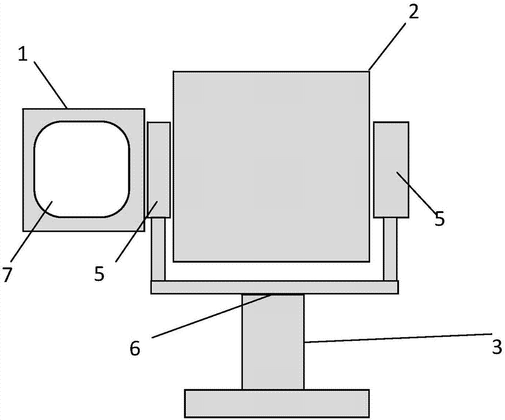
[0083] Such as figure 1 As shown, a photoelectric millimeter wave search and track device, said device has two working modes: search mode and tracking mode, said device includes: photoelectric detection component 1, millimeter wave ranging component 2, servo mechanism 3 and processing component 4; wherein, the photoelectric detection component 1 and the millimeter-wave ranging component 2 are installed together on the pitch component 5 of the servo mechanism 3 , and then the whole is carried by the azimuth component 6 of the servo mechanism 3 .

[0084] The millimeter-wave ranging component 2 is used to measure the distance and / or radial velocity of the target searched or tracked by the photoelectric detection component 1; it adopts a two-dimensional phase-scanning system, capable of performing two-dimensional phase-scanning in azimut...


PUM


Abstract

The invention discloses a photoelectric millimeter wave searching and tracking device. The device comprises a photoelectric detection component (1), a millimeter wave distance measuring component (2),a servo mechanism (3) and a processing component (4). The photoelectric detection component (1) is switched to the searching or tracking mode to perform target searching or tracking. The millimeter wave distance measuring component (2) is used for determining a two-dimensional phase sweep angle according to the target azimuth and pitch angle given by the photoelectric detection component (1), pointing the radar beams to the direction of the angle and measuring the target distance and/or radial speed. The photoelectric detection component (1) and the millimeter wave distance measuring component (2) are installed in the servo mechanism (3). The processing component (4) is used for controlling switching of the searching and tracking state of the device, processing the image information acquired by the photoelectric detection component (1) and extracting the target angle position information and controlling the millimeter wave distance measuring component (2) to perform distance measurement and/or radial speed measurement of the target of which the angle position information is acquired.

Description

technical field [0001] The invention belongs to the technical field of photoelectric search and tracking and millimeter wave radar, and relates to a method of using photoelectric detection equipment for target search or tracking, and millimeter wave radar to measure the distance of the target found by photoelectric search or the tracked target, so as to accurately and timely measure the position of the target. In particular, it relates to a photoelectric millimeter-wave three-coordinate search and tracking device and method. Background technique [0002] Small and ultra-small drones are easy to use, difficult to control, and easy to enter sensitive areas without permission, such as civil aviation airports, which pose serious hidden dangers to the safety of aircraft takeoff and landing. Small and ultra-small UAVs are typical "low, small and slow" targets characterized by low flying altitude, small target features, and slow flying speed, and because of their low flying altitud...

Claims


Application Information

Patent Timeline
Patent Type & Authority Applications(China)
IPC IPC(8): G01S13/08G01S13/89G01S7/02
CPCG01S7/02G01S13/08G01S13/89
Inventor 王全喜杨军李庶中孙健李越强沈宏李洁赵东伟鉴福生
Owner 中国人民解放军92232部队
Why Eureka
Try Eureka