

Method and apparatus for locating the trajectory of an object in motion
a technology of motion trajectory and detection system, which is applied in the direction of speed measurement using gyroscopic effects, sports equipment, devices using optical means, etc., can solve the problem that the system cannot address the saturation effect of the sun, the array is not exposed to ambient light, and cannot determine the velocity, nor the direction of the threa
- Summary
- Abstract
- Description
- Claims
- Application Information
AI Technical Summary
Benefits of technology
Problems solved by technology
Method used
Image

Examples
Embodiment Construction
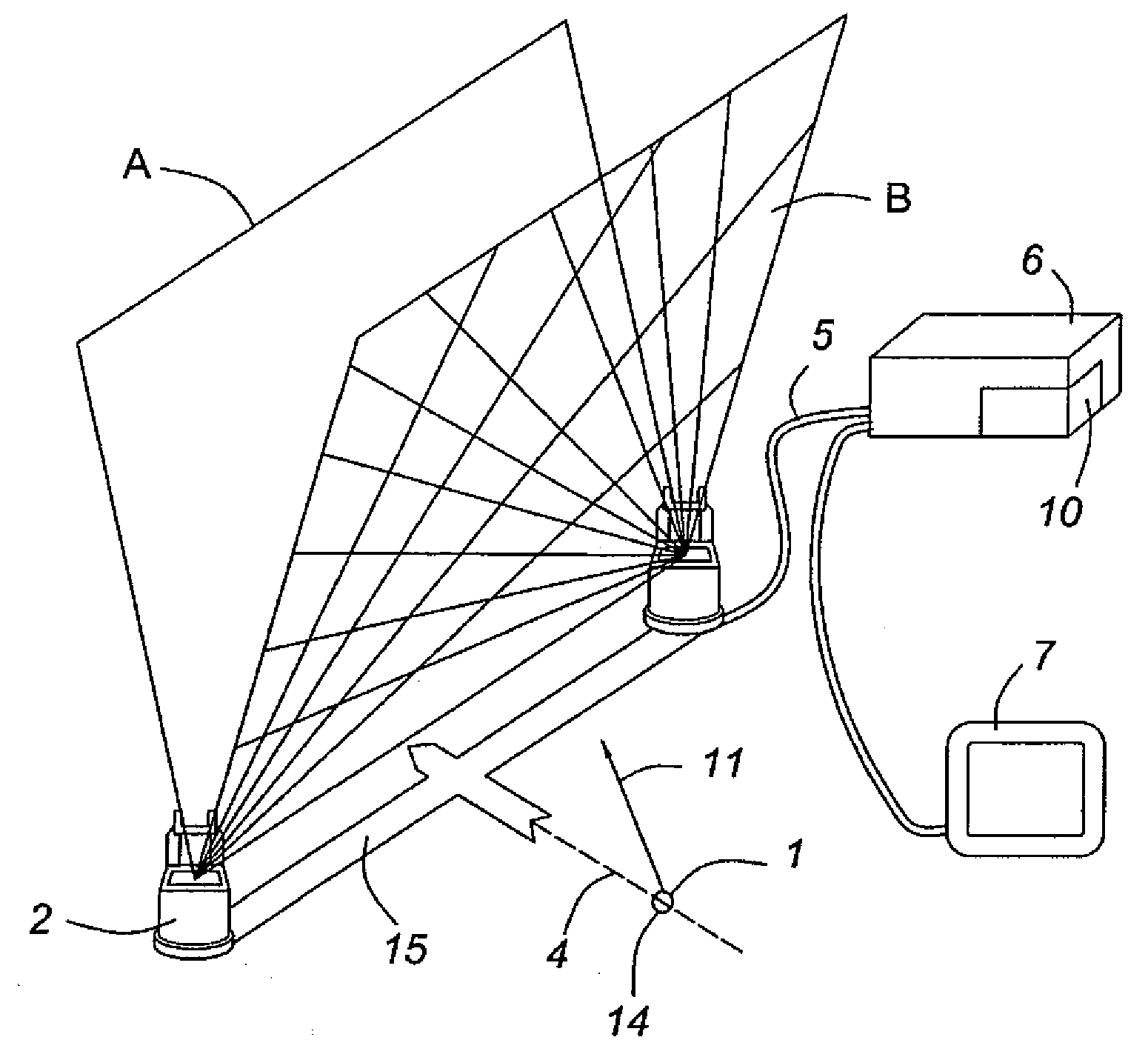
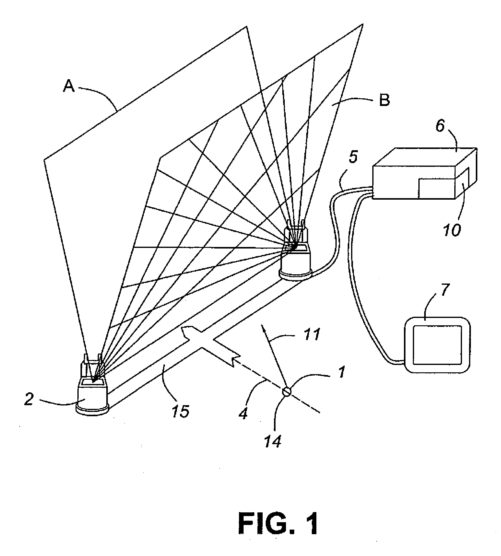
[0030]In one alternate embodiment of the invention, it would be desired to provide for a system which uses only a single pair of linear sensor arrays to provide a single sensing plane. Such a sensing plane system may be used to define a target zone that a projectile should pass through and to provide feedback to a user based upon whether or not the projectile has passed through said sensor zone. Alternatively, the single sensing plane could be used in combination with a known take-off location in order to calculate the trajectory of a projectile such as a golf ball. In such an embodiment, it might be advantageous to take a measurement of the time elapsed between the departure of the projectile from the known take-off location and the intersection of the projectile with the single sensing plane, in order to calculate the projectile's initial velocity. Further, by providing three or more sensing planes, it is possible to infer the curvature of the trajectory of a projectile such as a ...
PUM
 Abstract
Description
Claims
Application Information