Zipper head structure

a zipper head and zipper technology, applied in the direction of snap fasteners, slide fasteners, press-button fasteners, etc., can solve the problems that the conventional zipper head b>10/b> is not convenient when opening or closing the zipper

Inactive Publication Date: 2008-08-28
LEE CHIN CHANG
View PDF4 Cites 9 Cited by
  • Summary
  • Abstract
  • Description
  • Claims
  • Application Information

AI Technical Summary

Problems solved by technology

Therefore, the conventional zipper head 10 is not convenient when opening or closing the zipper.

Method used


Image

  • Zipper head structure
  • Zipper head structure
  • Zipper head structure

Examples


first embodiment

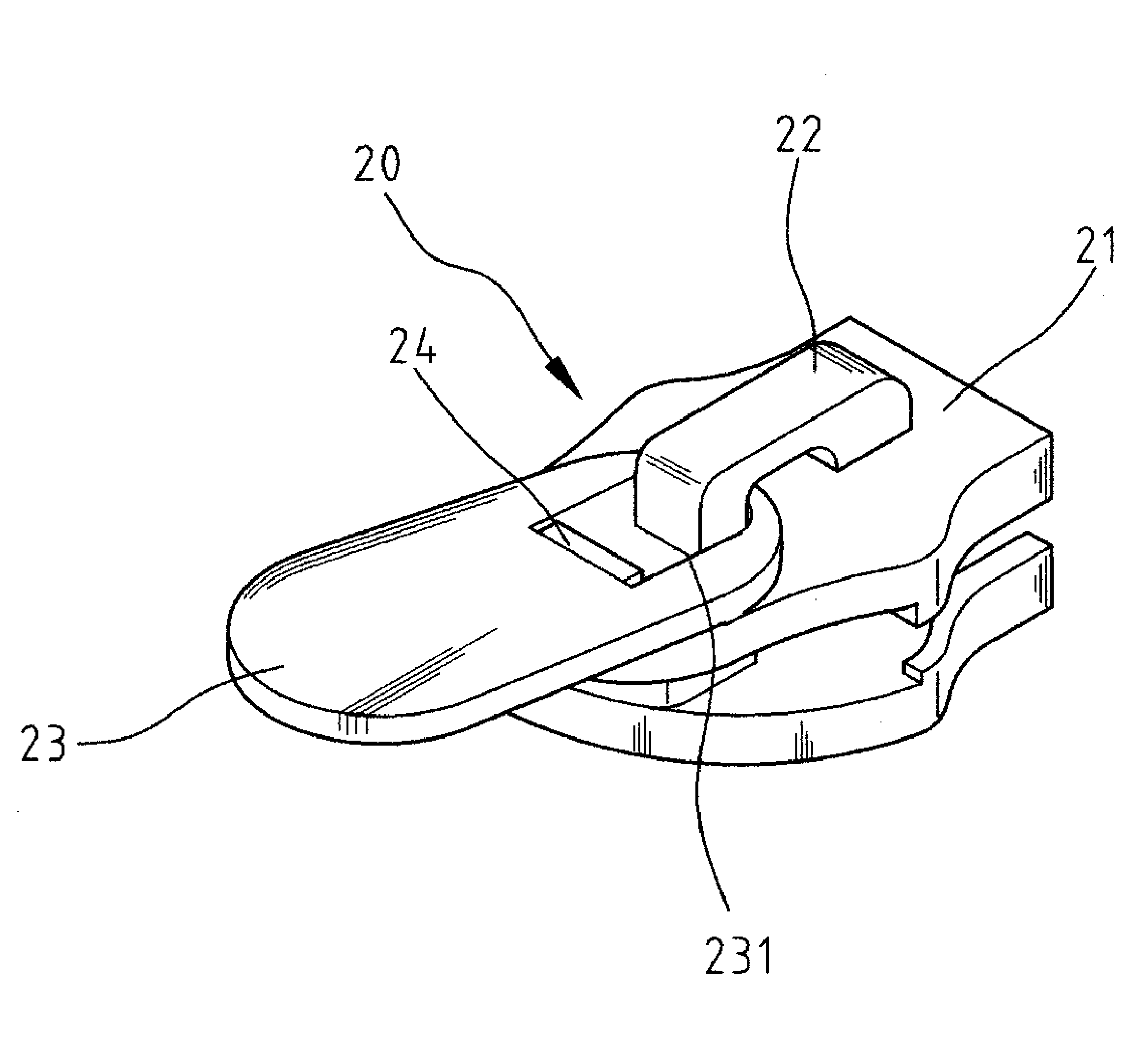
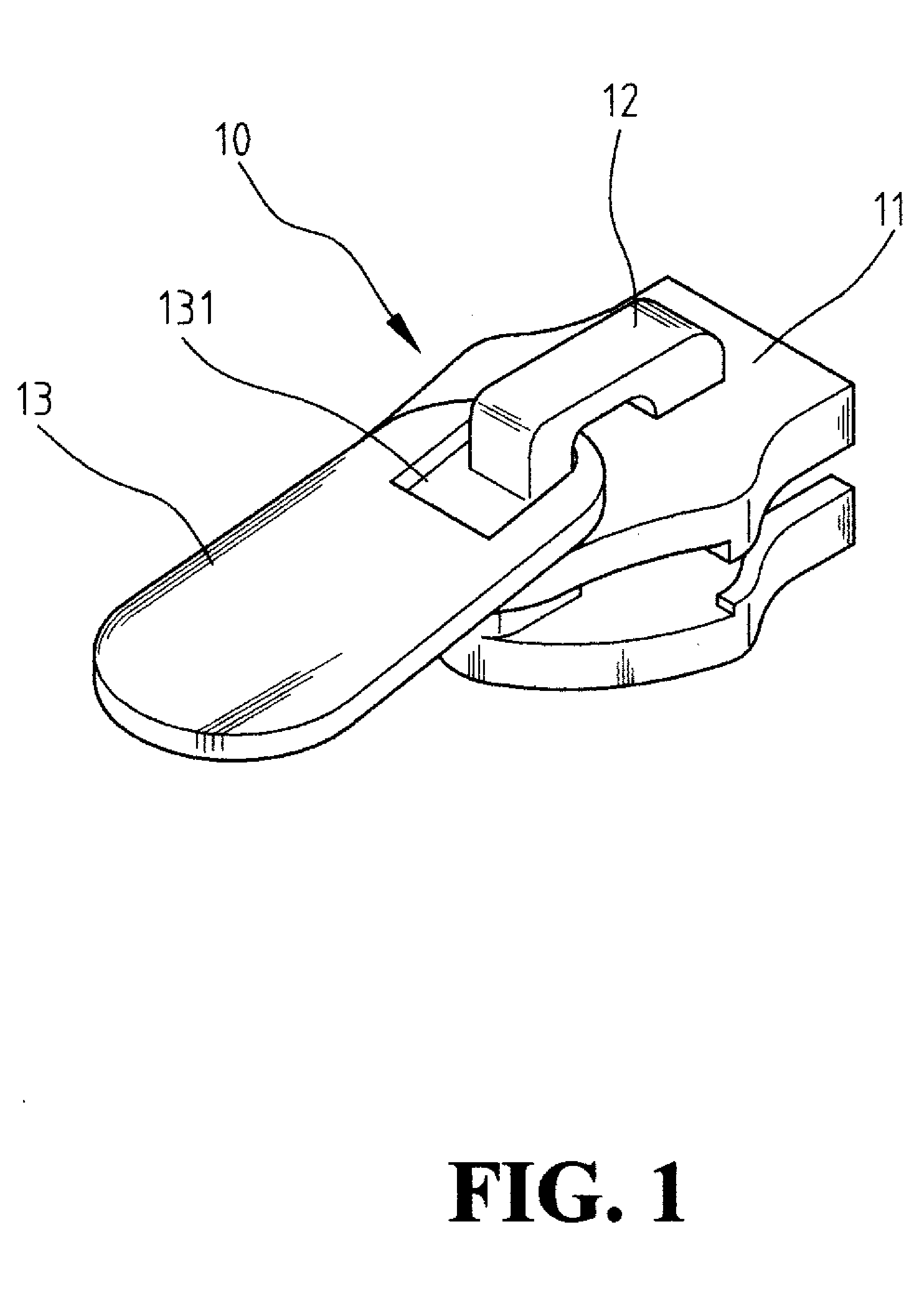
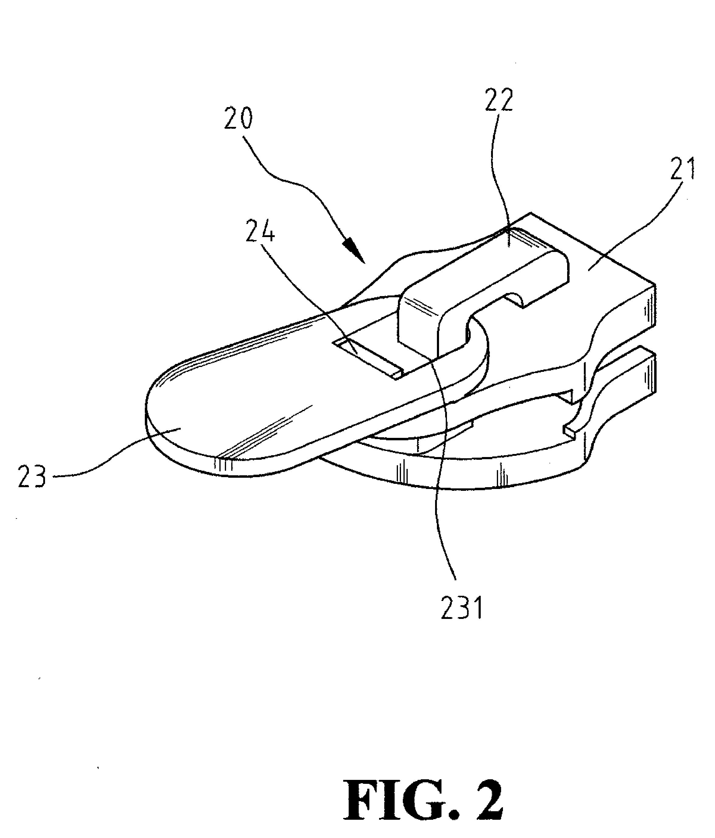
Please refer to FIG. 4, which shows a lateral view of first embodiment of the present invention. The blocker 24 is a wedge shape whose bottom gradually becomes smaller toward its top and the direction of the wedge could be from left to right or from front to back. In the embodiment, the blocker 24 has a first inclined surface 241 inclines upwards toward the rear end of the pull tag 20. When the pull tag 23 is put down, it first encloses the top end of the blocker 24, and when the pull tag 23 is further laid down, it engages on the first inclined surface 241 because of the slope of the inclined surface 241 and thereby the pull tag 23 is set in a predetermined angle (please refer to FIG. 5). Please refer to FIG. 6, following the same principle, a second inclined surface 242 of the blocker inclines upwards towards the front end of the blocker 24. The pull tag 23 has an engaging hole 232 corresponding to the second inclined surface, therefore, when the pull tag is released, the pull tag...

second embodiment

[0020]FIG. 6 shows a view of the present invention.

[0021]FIG. 7 shows a view of a second embodiment of the present invention after the pull tag eased.

third embodiment

[0022]FIG. 8 shows a view of the present invention.

[0023]FIG. 9 shows a view of a forth embodiment of the present invention.


PUM


Abstract

The present invention relates to a zipper head, and more particularly, to a zipper head with a pull tag that can be set and fixed to a predetermined angle. The zipper head of the present invention comprises a top plank and on the top plank there is a proboscis enclosing the pull tag, the characteristics are: the pull tag has an engaging hole; the top plank extending and forming a block corresponding to the engaging hole; when the pull tag is put down, the pull tag is engaged with the blocker by means of the engaging hole.

Description

1. FIELD OF THE INVENTION[0001]The present invention relates to a zipper head structure wherein the pull tag of the zipper head can be set and fixed to a predetermined angle.2. THE PRIOR ARTS[0002]Please refer to FIG. 1, which shows a perspective view of the prior art. The conventional zipper head 10 has a top plank 11 and a hook 12 disposed on the top plank 11. A pull tag 13 encloses the hook 12 to pull the zipper head 10 forwards and backwards. The pull tag 13 encloses the hook 12 by means of a hole 131 of the pull tag 13.[0003]Referring to FIG. 1, after using the pull tag 13 of the zipper head 10, normally it hangs on the upper surface of the top plank 11. Because the hole 131 is usually bigger than the external diameter of the hook 12, the pull tag 13 inclines downwardly with its tail pressing on the zipper. Therefore, to grip the pull tag 13 to move the zipper head 10, it must be raised away from the zipper, pinched, and then pulled to slide the zipper head 10 along the zipper ...

Claims


Application Information

Patent Timeline
Patent Type & Authority Applications(United States)
IPC IPC(8): A44B19/26
CPCY10T24/2586A44B19/26
Inventor LEE, CHIN-CHANG
Owner LEE CHIN CHANG
Why Eureka
Try Eureka