Magnetic Assemblies for Deposit Prevention

a magneto-magnetic assembly and deposit prevention technology, applied in the direction of wellbore/well accessories, sealing/packing, chemistry apparatus and processes, etc., can solve the problems of reduced production, costly start-up problems, paraffin or wax deposition, etc., and achieve the effect of preventing unwanted solid deposits and easy installation

Inactive Publication Date: 2008-08-28
BORST +2
View PDF28 Cites 9 Cited by
  • Summary
  • Abstract
  • Description
  • Claims
  • Application Information

AI Technical Summary

Benefits of technology

[0020]Accordingly, it is an object of the present invention to provide a magnetic apparatus and system, as well as an associated method for preventing the accumulation of unwanted solid deposits in production tubing that fully integrates with a hydrocarbon carrying conduit, such as a downhole tubing st

Problems solved by technology

The problem of unwanted solid deposition in oil wells, gas wells, surface production equipment, and in hydrocarbon flow lines has presented a challenge to the petroleum industry since the first wells were drilled more than one hundred years ago.
Although scale deposition is a major problem that interferes with the production of oil and gas, it is not the only problem.
Paraffin or wax deposition has also been recognized as a major problem from the inception of the oil industry all over the world, as has asphaltene formation.
The occurrence of these unwanted deposits in hydrocarbon producing conduits and related equipment can result in numerous problems, including reduced production and severe and often costly start up problems following pipeline shut down.
Other problems with unwanted deposits can include congealing hydrocarbons, interface problems, depositions in tank bottoms, high line pressures, plugged flow lines, under deposit corrosion, plugging of injection wells and filter plugging.
Scale deposit and accumulation is a significant problem to oil and gas producer wells.
Typically

Method used


Image

  • Magnetic Assemblies for Deposit Prevention
  • Magnetic Assemblies for Deposit Prevention
  • Magnetic Assemblies for Deposit Prevention

Examples


Embodiment Construction

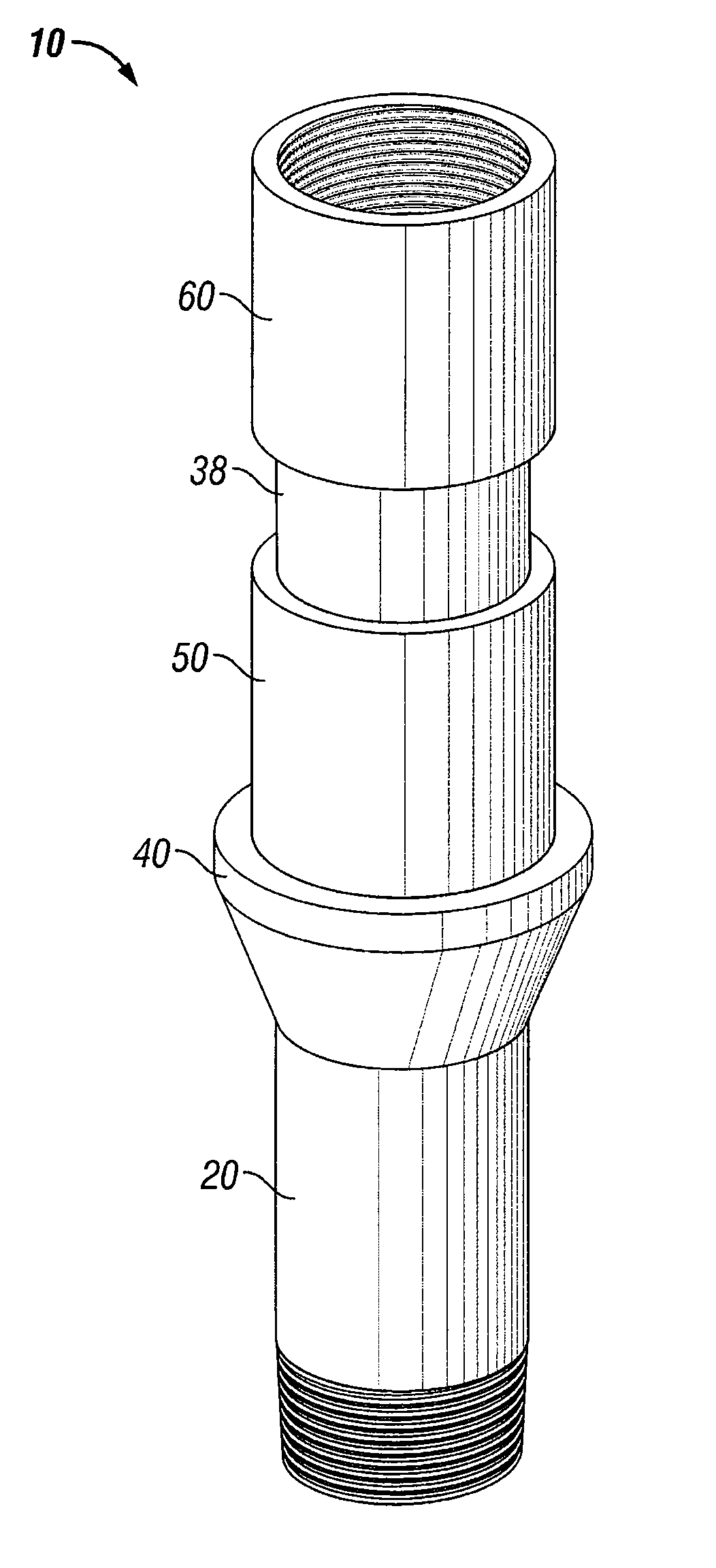
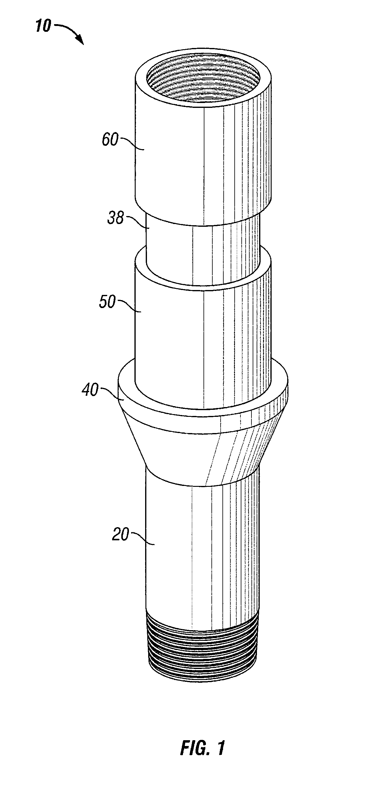
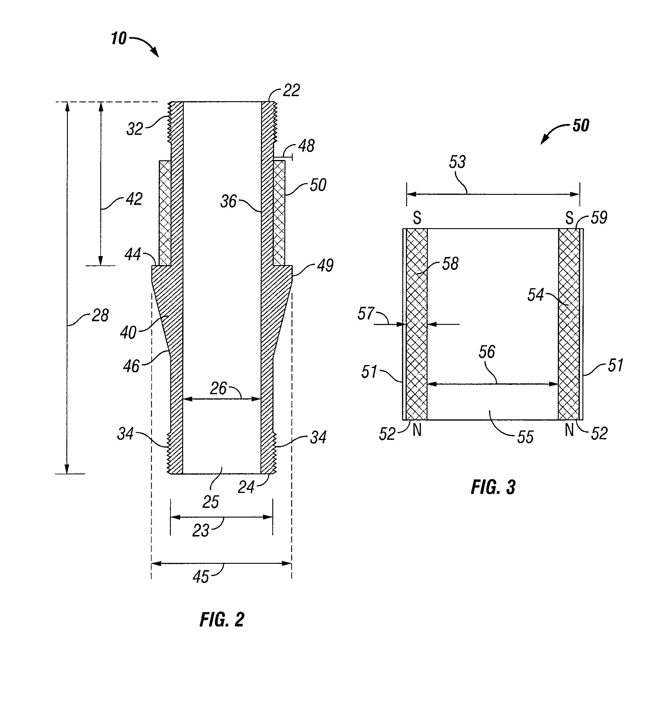
[0041]The Figures described above and the written description of specific structures and functions below are not presented to limit the scope of what Applicants have invented or the scope of the appended claims. Rather, the Figures and written description are provided to teach any person skilled in the art to make and use the inventions for which patent protection is sought. Those skilled in the art will appreciate that not all features of a commercial embodiment of the inventions are described or shown for the sake of clarity and understanding. Persons of skill in this art will also appreciate that the development of an actual commercial embodiment incorporating aspects of the present inventions will require numerous implementation-specific decisions to achieve the developer's ultimate goal for the commercial embodiment. Such implementation-specific decisions may include, and likely are not limited to, compliance with system-related, business-related, government-related and other c...


PUM


Abstract

An apparatus and method for controlling and/or minimizing the formation or accumulation of unwanted deposits on the inside of fluid flow paths by employing at various locations along the path an assembly of permanent magnets oriented such that the fluid flow is preferably from the North magnetic pole to the South magnetic pole.

Description

CROSS REFERENCE TO RELATED APPLICATIONS[0001]The present application is a continuation-in-part of co-pending U.S. patent application Ser. No. 11 / 221,677 filed Sep. 7, 2005, which claims priority to U.S. Provisional Patent Application Ser. No. 60 / 607,739 filed Sep. 7, 2004, the contents of all of which are incorporated herein by reference in their entirety.STATEMENT REGARDING FEDERALLY SPONSORED RESEARCH OR DEVELOPMENT[0002]Not applicable.REFERENCE TO APPENDIX[0003]Not applicable.BACKGROUND OF THE INVENTION[0004]1. Field of the Invention[0005]The invention relates to the inhibition of the formation of deposits inhibiting the flow of fluid in conduits and the like and, more specifically, to methods and devices for inhibiting the formation of unwanted deposits in downhole production equipment.[0006]2. Description of Related Art[0007]The problem of unwanted solid deposition in oil wells, gas wells, surface production equipment, and in hydrocarbon flow lines has presented a challenge to ...

Claims


Application Information

Patent Timeline
IPC IPC(8): E21B37/08
CPCC02F1/482E21B37/00E21B31/06
Inventor BORST, TERENCEPERIO, DUDLEY J.ALMS, DANIEL SCOTT
Owner BORST
Why Eureka
Try Eureka