
Flexible Wiring Cable

a flexible wiring and cable technology, applied in the direction of printed circuit aspects, printing, electrical apparatus construction details, etc., can solve the problems of large size of flexible wiring cables and complicated structure for connecting them to external signal sources, and achieve the effect of preventing bumping, convenient mounting, and compact structur

Inactive Publication Date: 2008-08-28
BROTHER KOGYO KK
View PDF5 Cites 0 Cited by
  • Summary
  • Abstract
  • Description
  • Claims
  • Application Information

AI Technical Summary

Benefits of technology

The patent text describes a flexible wiring cable for mounting circuit elements on it. The cable has a flat base with two surfaces, and leads and circuit elements are mounted on both surfaces. This design allows for a compact device and prevents interference between the circuit elements. The cable also has terminal electrodes that are easily connected to external signal sources and are exposed on both surfaces of the base. The cable can be easily mounted on a pulled-out part of the flexible wiring cable, and the wiring pitch is maintained without narrowing the width of the leads. The cable can also be designed with bumps for uniform pressure application and without interfering with the other circuit element. The cable is connected to an actuator of a recording head, and the number of nozzles and circuit elements can be increased without increasing the area of the cable.

Problems solved by technology

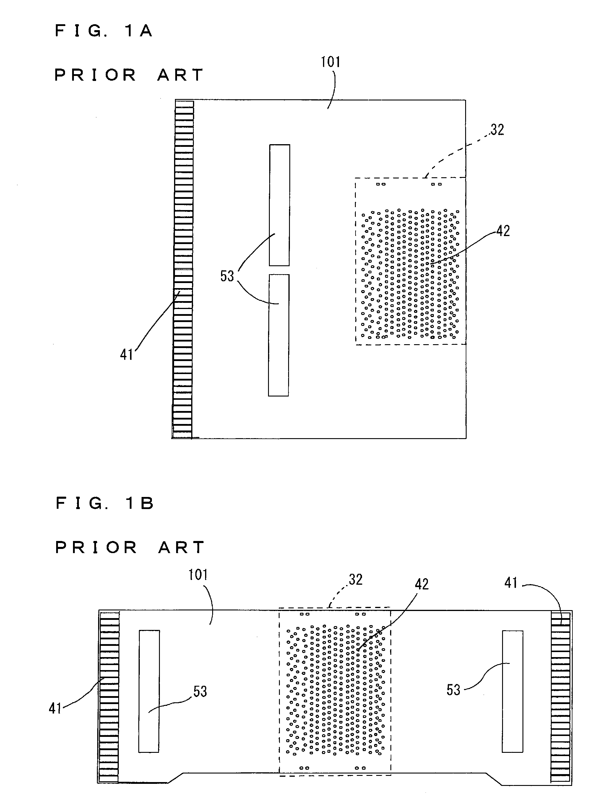
In addition, as shown in FIG. 1B, when the flexible wiring cable is pulled out in two directions away from the actuator and the circuit element is mounted on a pulled-out part respectively, the flexible wiring cable becomes large also and the structure for connecting it to the external signal source becomes complicated, which is a problem.

Method used


Image

  • Flexible Wiring Cable
  • Flexible Wiring Cable
  • Flexible Wiring Cable

Examples


Embodiment Construction

[0028]An embodiment will be described with reference to the drawings hereinafter.

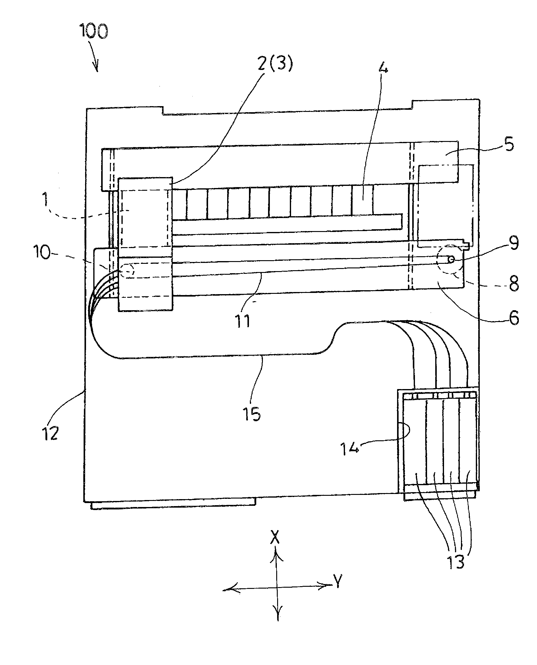
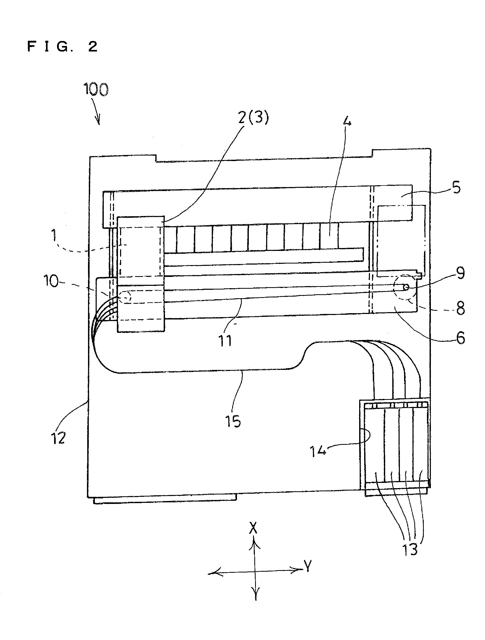
[0029]FIG. 2 is a schematic plan view showing a recoding device 100 including a flexible wiring cable 1 of the embodiment on which a circuit element is mounted. This recording device 100 may be used in a single printer or may be used as a printer function (recording part) in a multifunctional device having a plurality of functions such as a facsimile function and a copy function.

[0030]As shown in FIG. 2, the recording device 100 includes a recording head 3 mounted on a carriage 2 and a platen 4 opposed to a lower surface of the recording head 3. A first guide member 5 and a second guide member 6 extend in a main scanning direction (Y-axis direction) of the carriage 2 and the carriage 2 reciprocates along them. The recording head 3 is mounted on the carriage 2 in such a manner that a nozzle 7 (refer to FIG. 5) is exposed so as to be opposed to the platen 4.

[0031]A sheet as a recording medium is transferr...


PUM


Abstract

A flexible wiring cable includes a flexible flat base, and a plurality of first and second leads wired on first and second surfaces of the base respectively. First and second circuit elements are mounted on the first and second leads respectively. A plurality of terminal electrodes is provided on the first surface of the base. The terminal electrodes include a plurality of first terminal electrodes formed on the first leads and a plurality of second terminal electrodes formed on the second leads, being exposed to the outside of the first surface side via through holes formed in the base.

Description

CROSS-REFFERENCE TO RELATED APPLICATION[0001]This Nonprovisional application claims priority under 35 U.S.C. §119(a) on Patent Application No. 2007-42617 filed in Japan on Feb. 22, 2007, the entire contents of which are hereby incorporated by reference.BACKGROUND[0002]The present invention relates to a flexible wiring cable on which a circuit element is mounted.[0003]As the flexible wiring cable mounted with the circuit element, a wiring cable or the like for transmitting a drive signal based on print data to an actuator of a recording head discharging ink is known, for example. As for the recording head, a structure including a cavity part having many nozzles and an ink supply path, and an actuator having an active part corresponding to each nozzle is disclosed in Japanese Patent Application Laid-Open No. 2007-7955, for example. Thus, the actuator and an external signal source are connected by the flexible wiring cable mounted with the circuit element.[0004]The drive signal is supp...

Claims


Application Information

Patent Timeline
Patent Type & Authority Applications(United States)
IPC IPC(8): H05K1/00H01R12/24
CPCH05K1/189H05K3/363H05K2201/0367H05K2201/0394H05K2201/094B41J2002/14491H05K2201/10674H05K2203/1572B41J2/14209B41J2002/14217B41J2002/14225H05K2201/09472
Inventor HIWADA, SHUHEI
Owner BROTHER KOGYO KK
Learn More