
Motor controller and electric power steering apparatus

a technology of motor controller and electric steering apparatus, which is applied in the direction of dynamo-electric converter control, gearing, dynamo-electric gear control, etc., can solve the problems of inability to properly correct the d-axis and q-axis current command values, unavoidable torque ripple generation, and inability of prior art apparatus to correspond, etc. to achieve the effect of suppressing the generation of torque rippl

Inactive Publication Date: 2008-08-28
JTEKT CORP
View PDF36 Cites 16 Cited by
  • Summary
  • Abstract
  • Description
  • Claims
  • Application Information

AI Technical Summary

Benefits of technology

[0023]An objective of the present invention is to provide a motor controller and an electric power steering apparatus which effectively suppress the generation of torque ripple caused by distortion of an induced voltage waveform even at a time of executing a field weakening control.

Problems solved by technology

However, since the apparatus according to the prior art is structured on the assumption that the d-axis noninteracting control is executed (Id*=0), the prior art apparatus cannot correspond to the field weakening control mentioned above.
Accordingly, it is impossible to properly correct the d-axis and q-axis current command values at a time of the field weakening control, and the generation of torque ripple is unavoidable.

Method used


Image

  • Motor controller and electric power steering apparatus
  • Motor controller and electric power steering apparatus
  • Motor controller and electric power steering apparatus

Examples


Embodiment Construction

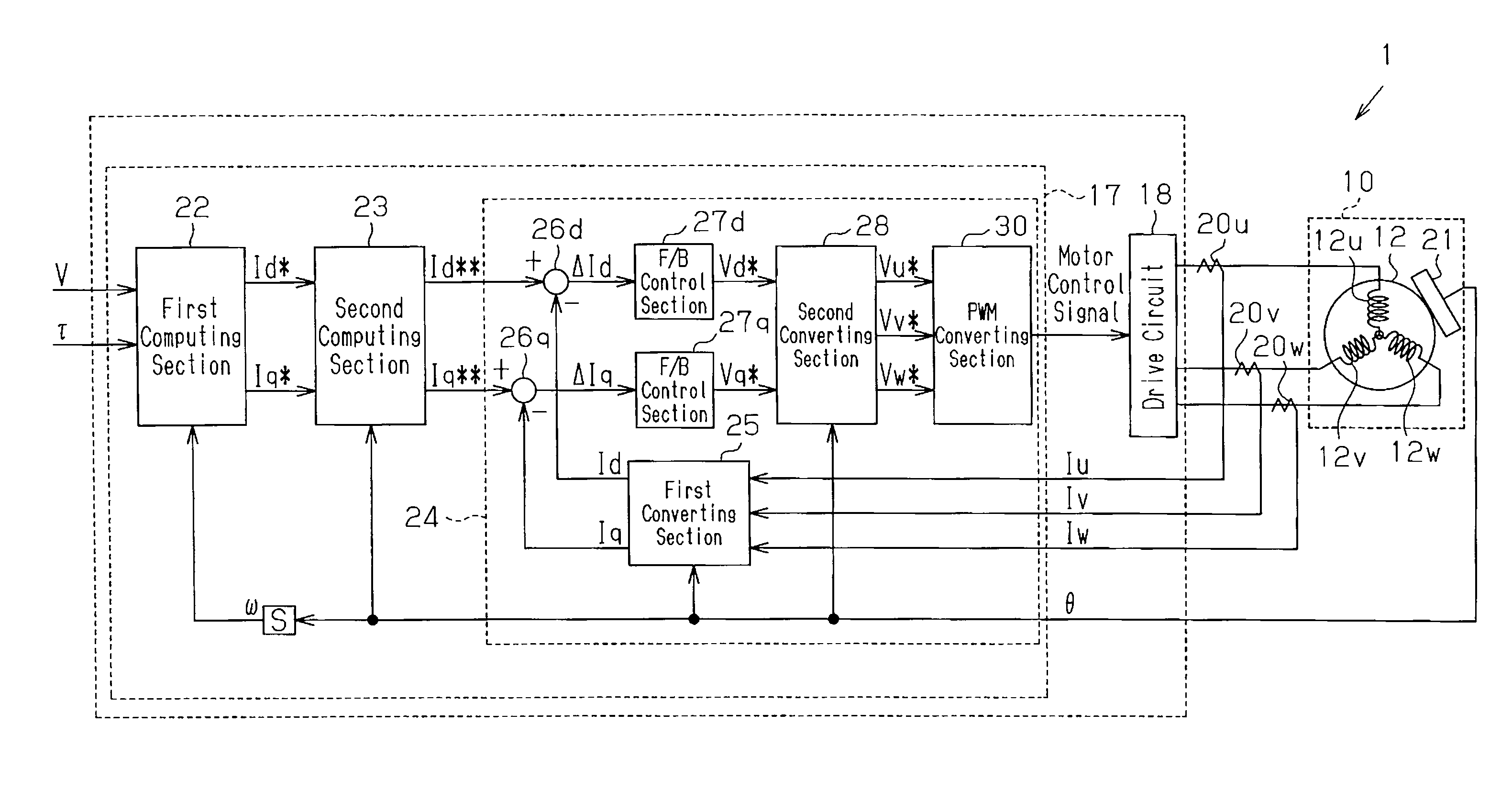
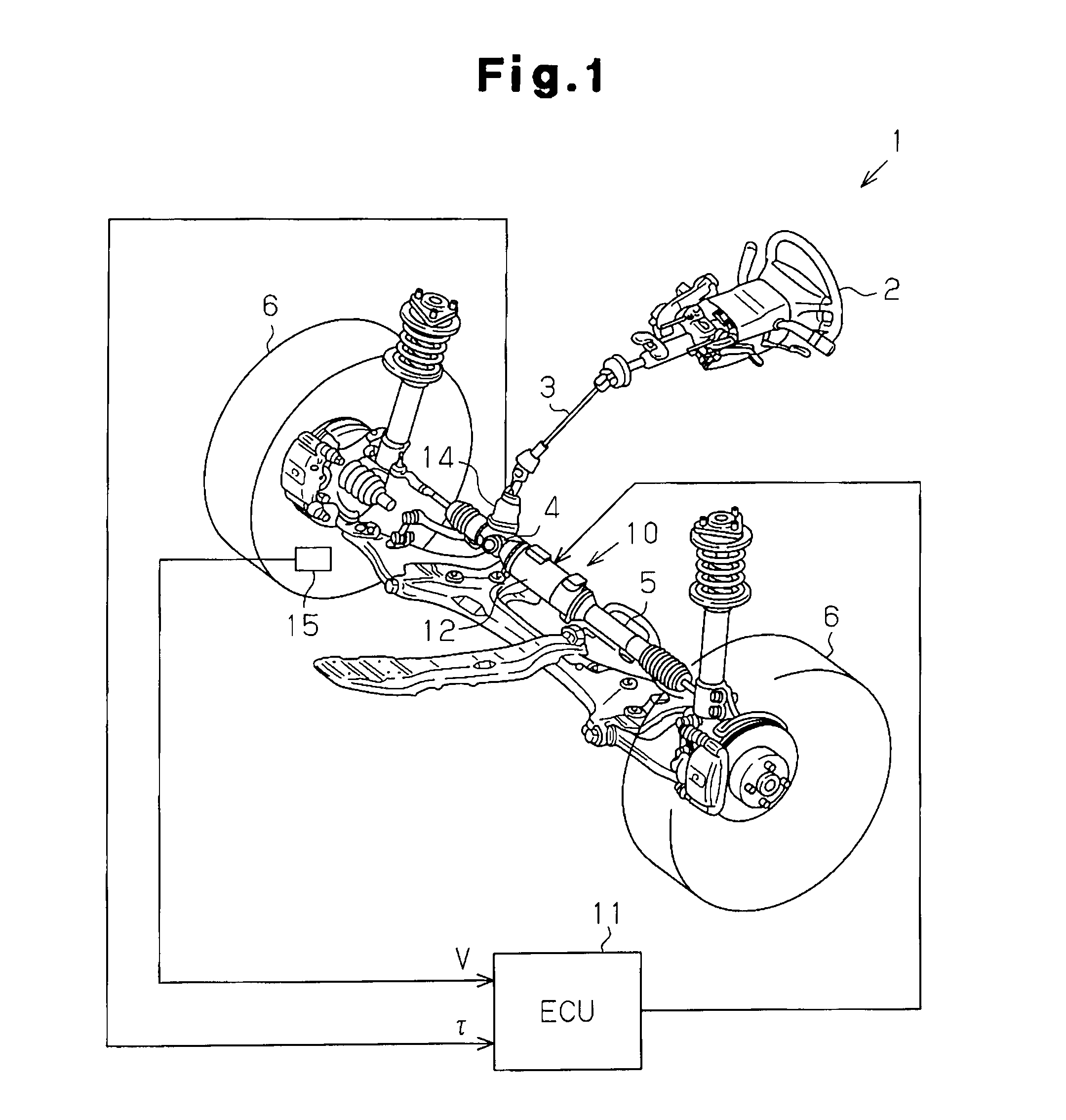
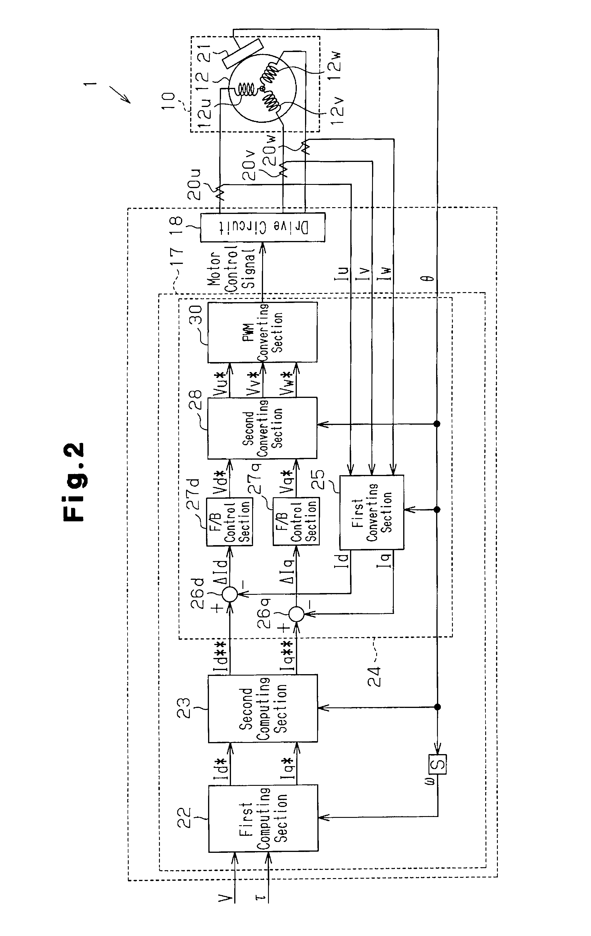
[0030]A description will be given below of an electric power steering apparatus (EPS) according to one embodiment of the present invention with reference to the accompanying drawings.

[0031]As shown in FIG. 1, a steering shaft 3 is fixed to a steering wheel 2. The steering shaft 3 is coupled to a rack 5 by a rack and pinion mechanism 4. Rotation of the steering shaft 3 accompanying a steering operation is converted into a linear reciprocation of the rack 5 by the rack and pinion mechanism 4. Further, the steering angle of steerable wheels 6 is changed on the basis of the linear reciprocation of the rack 5.

[0032]The EPS 1 is provided with an EPS actuator 10 and an ECU 11. The EPS actuator 10 is a steering force assisting device applying an assist force for assisting a steering operation to a steering system. The ECU 11 is control means controlling the actuation of the EPS actuator 10.

[0033]The EPS actuator 10 is a rack type EPS actuator in which a motor 12 serving as a drive source is...


PUM


Abstract

A second computing section executing a compensation control is provided with a third computing section computing a d-axis correction amount, and a fourth computing section computing a q-axis correction amount. The respective computing sections compute a d-axis correction coefficient and a q-axis correction coefficient corresponding to an rotation angle by referring to a map. The respective computing sections compute the d-axis correction amount and the q-axis correction amount on the basis of an arithmetic expression constituted by a first term obtained by multiplying a correction coefficient relating to an object axis by a q-axis current command value and a second term obtained by multiplying a correction coefficient relating to an auxiliary axis by a d-axis current command value. The second computing section computes a d-axis current command value and a q-axis current command value which do not generate a torque ripple caused by a distortion of an induced voltage waveform, by adding the d-axis correction amount and the q-axis correction amount to the d-axis current command value and the q-axis current command value.

Description

[0001]This application is based on and claims priority from Japanese Patent Application No. 2007-046104 filed on Feb. 26, 2007, the entire contents of which are incorporated herein by reference.BACKGROUND OF THE INVENTION[0002]The present invention relates to a motor controller and an electric power steering apparatus.[0003]Conventionally, a power steering apparatus for a vehicle includes an electric power steering apparatus (EPS) provided with a motor as a drive source. The EPS has a lot of flexibility in the arrangement and an energy consumption is small in comparison with a hydraulic power steering apparatus. Accordingly, in recent years, the use of the EPS in many kinds of vehicles has been studied.[0004]A motor has inherently has a fluctuation of an output torque, such as a cogging torque, a torque ripple caused by a distortion of an induced voltage waveform generated in a motor coil or the like. However, in the EPS, the fluctuation of the output torque mentioned above is refle...

Claims


Application Information

Patent Timeline
Patent Type & Authority Applications(United States)
IPC IPC(8): H02P21/00F16H35/00H02P6/10B62D5/04B62D6/00B62D119/00H02P6/06H02P6/08
CPCB62D5/046H02P21/06H02P21/0035H02P21/22
Inventor SUZUKI, HIROSHI
Owner JTEKT CORP
Learn More