DC-DC Converter that Includes a High Frequency Power MESFET Gate Drive Circuit

a technology of dc-dc converter and gate drive circuit, which is applied in the direction of dc-dc converter, power conversion system, instruments, etc., can solve problems such as not being useful, and achieve the effects of low on-state resistance, low turn-on voltage, and low off-state drain leakag

Inactive Publication Date: 2008-08-28
ADVANCED ANALOGIC TECHNOLOGIES INCORPORATED
View PDF25 Cites 45 Cited by
  • Summary
  • Abstract
  • Description
  • Claims
  • Application Information

AI Technical Summary

Benefits of technology

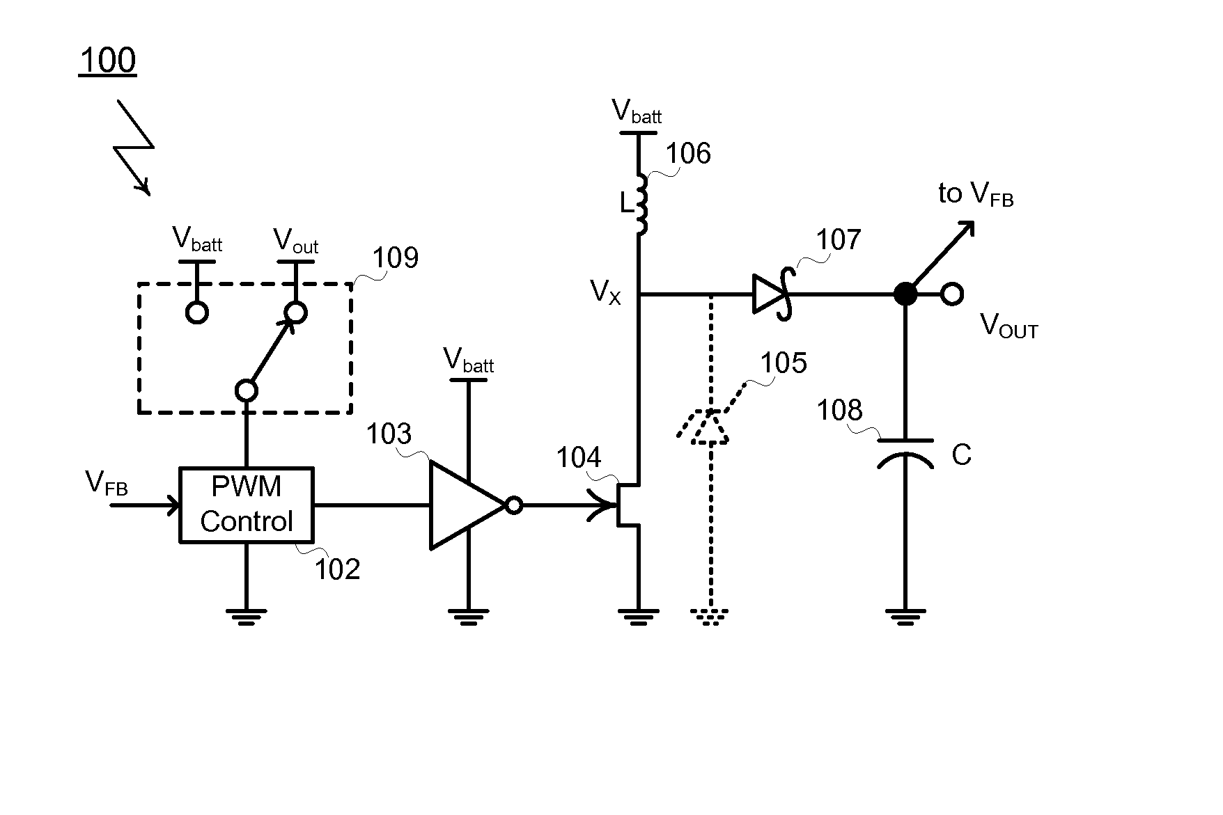
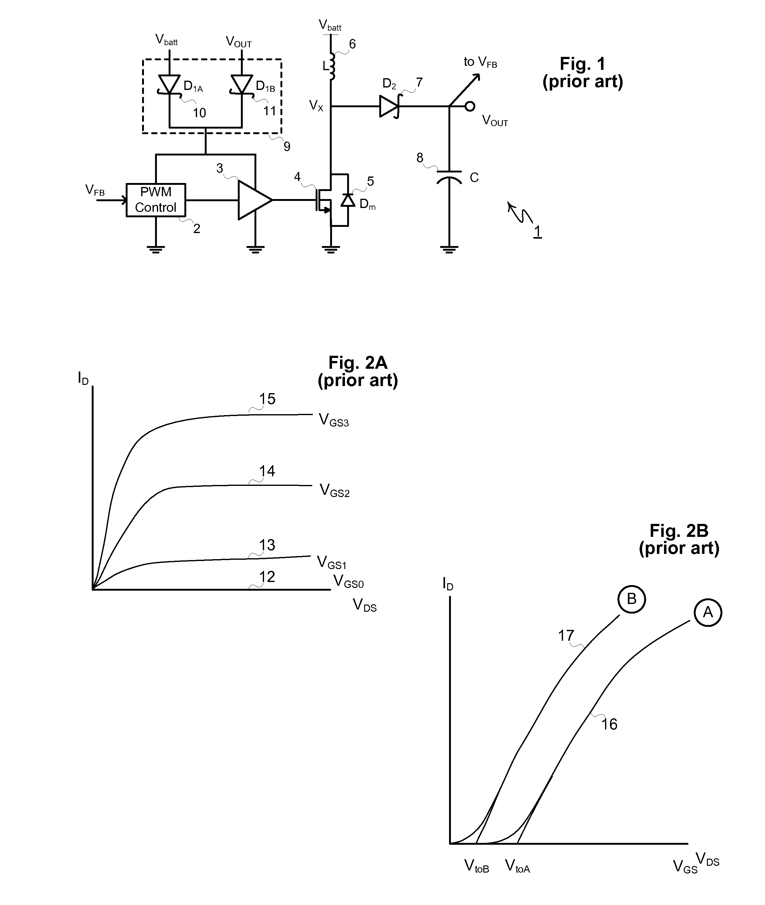
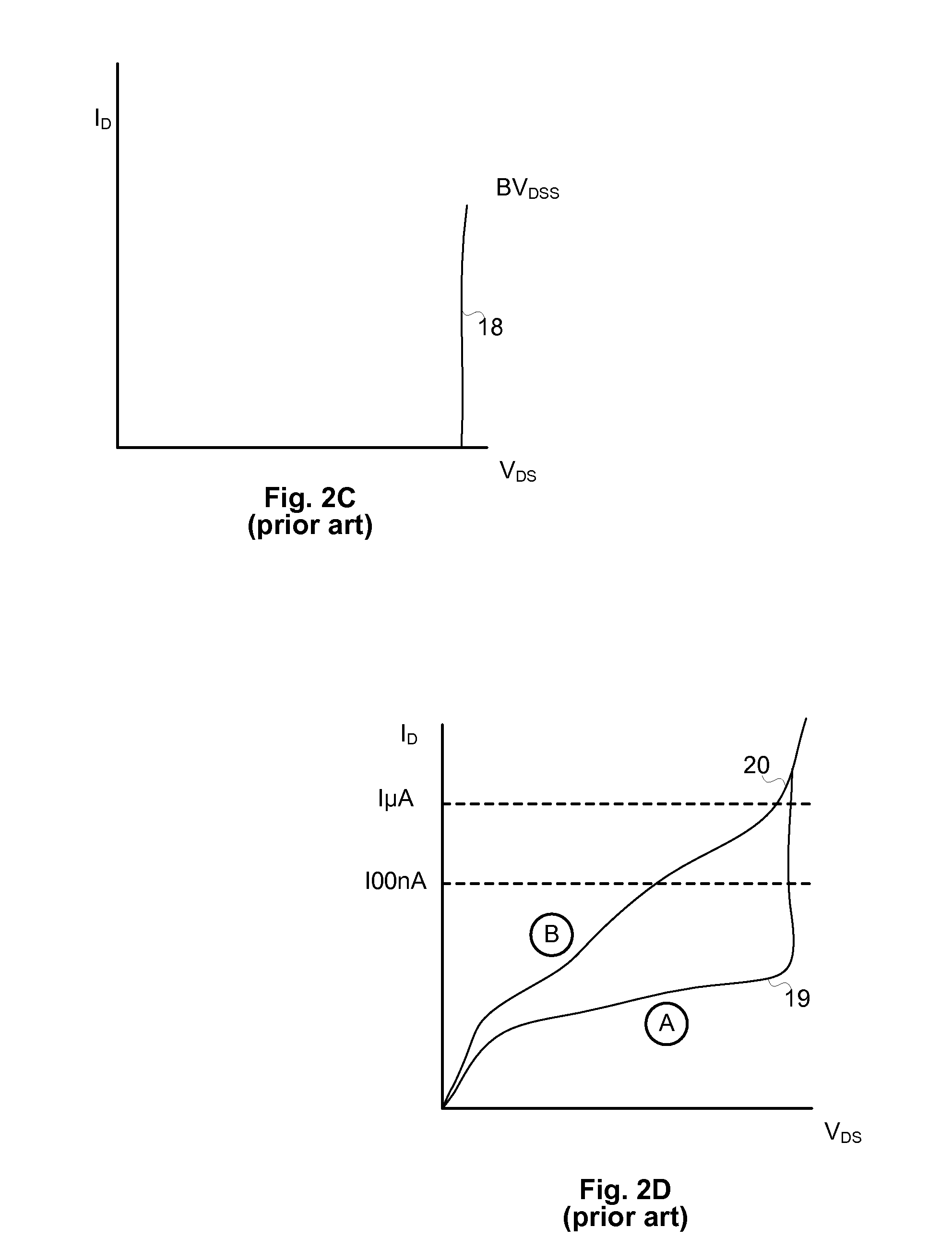
[0031]The present invention includes inventive matter regarding gate drive methods that enable the use of power MESFETs in switching regulators. The gate drive methods are preferably, but not necessarily useful in combination with the type of MESFET described in the US patent application entitled “Rugged MESFET for Power Application.” This type of MESFET, referred to in this document as a “Type A” MESFET is a normally off device with low on-state resistance, low off-state drain leakage, minimal gate leakage, rugged (non-fragile) gate characteristics, robust avalanche characteristics, low turn-on voltage, low input capacitance (i.e. low gate charge), and low internal gate resistance (for fast signal propagation across the device). These characteristics make Type A MESFETs particularly suitable as power switches in Boost converters, Buck converters, Buck-boost converters, flyback converters, forward converters, full-bridge converters, and more.
[0032]Using Type A MESFETs as power switches and synchronous rectifiers in DC-to-DC switching converters requires special gate drive circuitry and techniques to prevent overdrive of the MESFET's Schottky gate inputs. Overdrive must be prevented to protect the power MESFETs from damage, avoid unwanted switching oscillations, and to avoid gate drive losses that reduce overall converter efficiency.
[0040]Yet another method for static drive of a MESFET modifies the CMOS inverter by adding a series of one or more diodes between the P-channel and N-channel MOSFETs. Each diode decreases the maximum voltage at the gate of the MESFET by one forward voltage VF is approximately 0.7V per diode. The number of diodes can be adjusted depending on the battery voltage. Shunting transistors may be added in parallel with one or more of the diodes. By enabling one or more of these transistors, the voltage drop over the series of diodes may be dynamically adjusted to match battery output, thereby limiting the range of voltages imposed on the MESFET's gate.Dynamic Gate Drivers with Overdrive Protection for Low-Side MESFETS

Problems solved by technology

The gate drive methods are preferably, but not necessarily useful in combination with the type of MESFET described in the US patent application entitled “Rugged MESFET for Power Application.” This type of MESFET, referred to in this document as a “Type A” MESFET is a normally off device with low on-state resistance, low off-state drain leakage, minimal gate leakage, rugged (non-fragile) gate characteristics, robust avalanche characteristics, low turn-on voltage, low input capacitance (i.e. low gate charge), and low internal gate resistance (for fast signal propagation across the device).

Method used


Image

  • DC-DC Converter that Includes a High Frequency Power MESFET Gate Drive Circuit
  • DC-DC Converter that Includes a High Frequency Power MESFET Gate Drive Circuit
  • DC-DC Converter that Includes a High Frequency Power MESFET Gate Drive Circuit

Examples


Embodiment Construction

[0061]The present invention includes inventive matter regarding specialized gate drive for a proposed power MESFET which we shall refer to in this document as a “type A” device.

[0062]Before describing the gate drive subject matter, a short description of the “type A” device is presented. A more complete description of the “type A” device and its applications is included the related applications previously identified.

[0063]FIG. 4D illustrates how the previously described “type B” depletion-mode device would need to be adjusted to make a power switch with useful characteristics (i.e., the “type A” device). Similar to an enhancement mode MOSFET, the proposed “type A” MESFET needs to exhibit a near zero value of IDSS current, i.e. the current IDmin shown as line 50 should be as low as reasonably possible at VGS0=0. Biasing the Schottky gate with positive potentials of VGS1, VGS2, and VGS3 results in increasing currents 51, 52, and 53, respectively, clamped to some maximum value by condu...


PUM


Abstract

A DC-DC converter that includes a high frequency power MESFET gate drive circuit is provided. The gate drive circuits are intended to be used in switching regulators where at least one switching device is an N-channel MESFET. For regulators of this type, the gate drive circuits provide gate drive at the correct voltage to ensure that MESFETs are neither under driven (resulting in incorrect circuit operation) nor over driven (resulting in MESFET damage or excess current or power loss).

Description

RELATED APPLICATIONS[0001]This application is a divisional of pending U.S. patent application Ser. No. 11 / 307,199. The disclosures of the following related U.S. patent applications are incorporated in this document by reference: Ser. No. 11 / 307,200, Ser. No. 11 / 307,201, Ser. No. 11 / 307,202, Ser. No. 11 / 307,203 and Ser. No. 11 / 307,204.BACKGROUND OF INVENTION[0002]Voltage regulators are used commonly used in battery powered electronics to eliminate voltage variations resulting from the discharging of the battery and to supply power at the appropriate voltages to various microelectronic components such as digital ICs, semiconductor memory, display modules, hard disk drives, RF circuitry, microprocessors, digital signal processors and analog ICs. Since the DC input voltage must be stepped-up to a higher DC voltage, or stepped down to a lower DC voltage, such regulators are referred to as DC-to-DC converters.[0003]Step-down converters are used whenever a battery's voltage is greater than...

Claims


Application Information

Patent Timeline
Patent Type & Authority Applications(United States)
IPC IPC(8): G05F1/44G05F1/10
CPCH03K17/08122H02M3/158
Inventor WILLIAMS, RICHARD K.
Owner ADVANCED ANALOGIC TECHNOLOGIES INCORPORATED
Why Eureka
Try Eureka