Coil arrangement for electromagnetic tracking method and system

a coil arrangement and electromagnetic tracking technology, applied in the field of coil arrangement for electromagnetic tracking, can solve the problems of inability to accurately track the distance of an em field generator above or below the plane, inability to provide a sufficient estimate of position and/or orientation, and difficulty in processing determination

Active Publication Date: 2008-08-28
STRYKER EURO OPERATIONS HLDG LLC
View PDF46 Cites 98 Cited by
  • Summary
  • Abstract
  • Description
  • Claims
  • Application Information

AI Technical Summary

Problems solved by technology

Although the previously described methods may provide sufficient accuracy, there are several instances in which the sensors located about the periphery of a region in a single plane do not provide a sufficient estimate of position and / or orientation.
For example, when four EM receivers are located in a single plane (e.g., on top of a surgery table) processing may be unable to accurately track the distance of an EM field generator above or below the plane.
Further, even if the distance is determined, it may be difficult (if not impossible) for processing to determine on which side of the plane the EM field generator is located.
Thus, processing is unable to resolve on which side of the plane the EM field generator is located.
When an ICSA transmitter or receiver needs to be mounted in the tip of a surgical instrument, space is restricted, making the use of a three coil device difficult.

Method used


Image

  • Coil arrangement for electromagnetic tracking method and system
  • Coil arrangement for electromagnetic tracking method and system
  • Coil arrangement for electromagnetic tracking method and system

Examples


Embodiment Construction

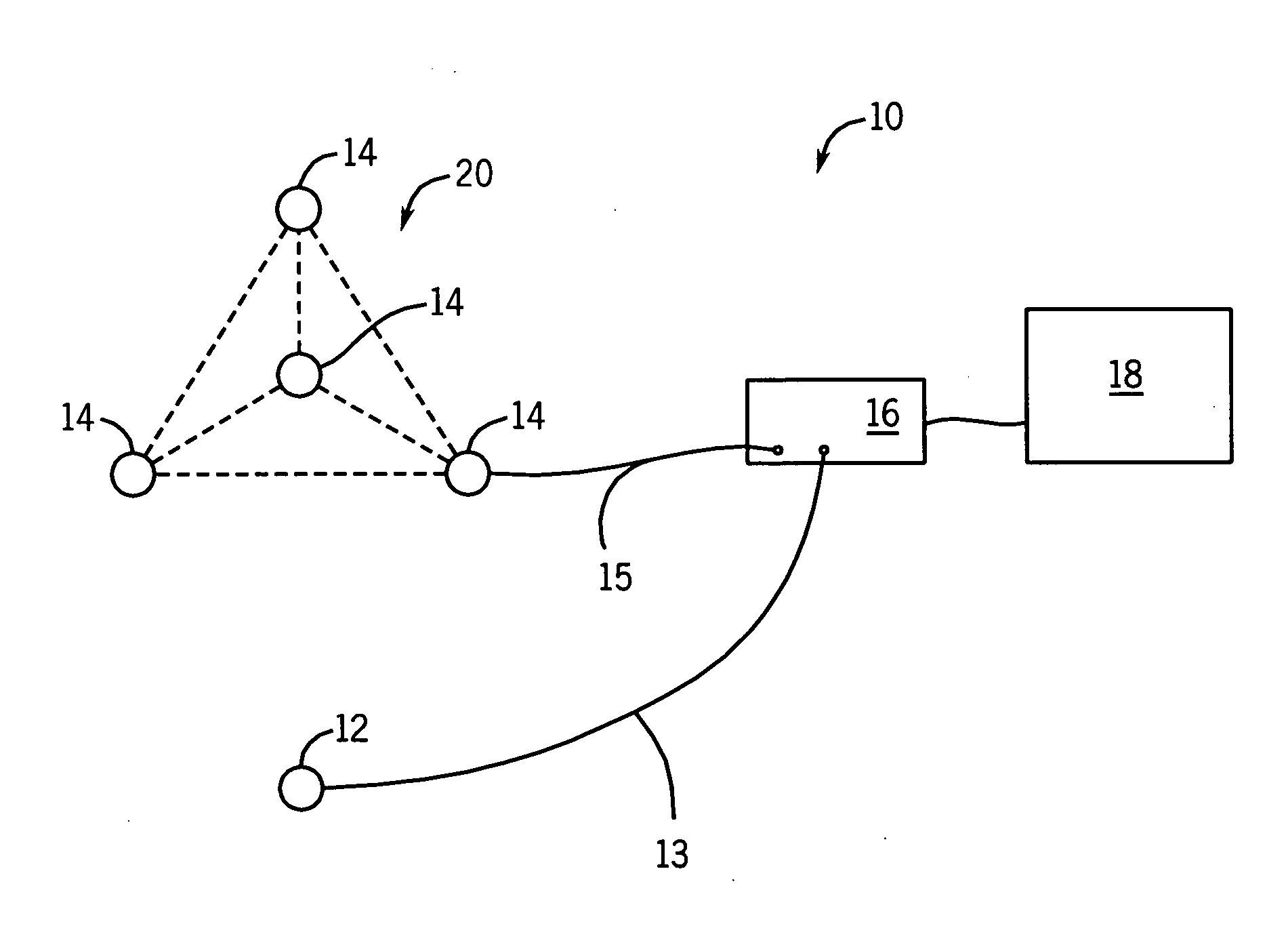
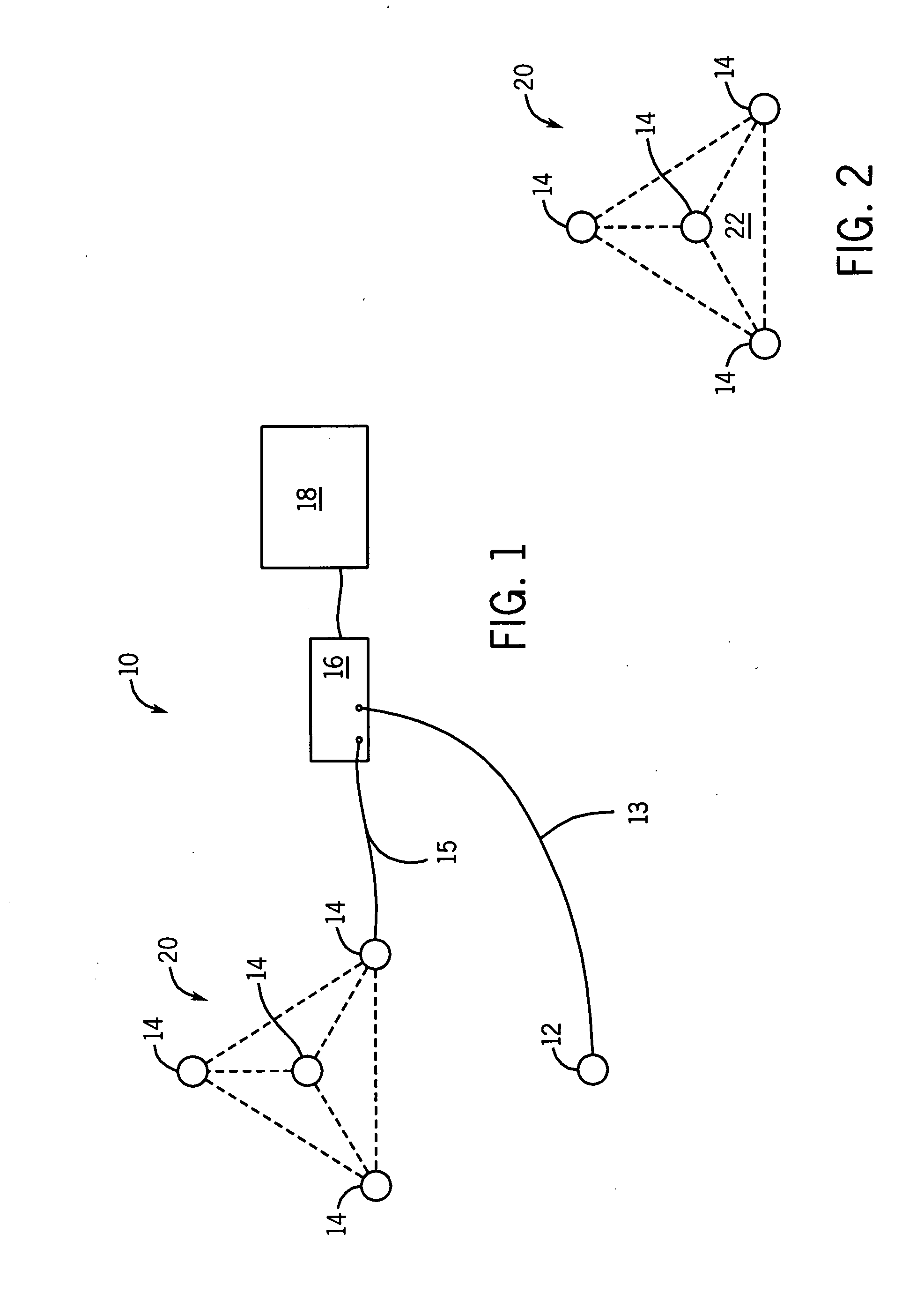
[0019]Referring now to FIG. 1, a tracking system 10 in accordance with an embodiment of the present technique is illustrated. The tracking system 10 may generally include multiple tracking components. As depicted, the tracking components may include an electromagnetic (EM) coil arrangement 20 with a plurality of EM sensors 14, at least one complementary EM sensor 12, a processor 16 and a user interface 18. The at least one complementary EM sensor 12 may be coupled to at least one instrument or device 26, as shown in FIG. 4.

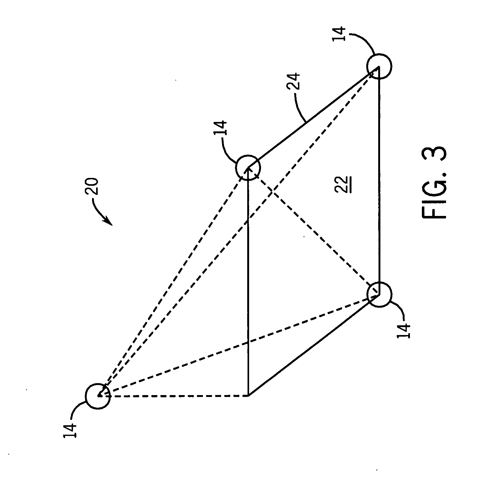
[0020]In the illustrated embodiment, the EM coil arrangement 20 comprises an array of EM sensors 14 arranged around a volumetric region 22. The array of EM sensors 14 may be formed from magnetic dipoles (e.g., coils, current loops, or electromagnets) capable of producing a dipole magnetic field when a current is applied or induced across them. In some embodiments, the EM sensors 14 may employ industry-standard coil architecture (ISCA) type coils, a single dipole c...


PUM


Abstract

An electromagnetic tracking coil arrangement, comprising three co-planar electromagnetic sensors and a fourth electromagnetic sensor that is not co-planar with the three co-planar sensors, wherein the three co-planar electromagnetic sensors and the fourth electromagnetic sensor are each located at a vertex of a tetrahedron.

Description

BACKGROUND[0001]This disclosure relates generally to tracking systems that use magnetic fields to determine the position and orientation of an object, such as systems used for tracking instruments and devices during surgical interventions and other medical procedures. More particularly, this disclosure relates to a system and method for electromagnetic tracking that utilizes a compact coil arrangement.[0002]Tracking systems have been used in various industries and applications to provide position information relating to objects. For example, electromagnetic tracking may be useful in aviation applications, motion sensing applications, and medical applications. In medical applications, tracking systems have been used to provide an operator (e.g., a physician) with information to assist in the precise and rapid positioning of a medical device located in or near a patient's body. In general, an image may be displayed on a monitor to provide positioning information to an operator. The im...

Claims


Application Information

Patent Timeline
Patent Type & Authority Applications(United States)
IPC IPC(8): G01B7/14
CPCA61B19/52A61B2019/5475A61B2019/5251A61B19/5244A61B34/20A61B90/36A61B2034/2051A61B2090/3975
Inventor ANDERSON, PETER TRANEUS
Owner STRYKER EURO OPERATIONS HLDG LLC
Why Eureka
Try Eureka