High field magnetic resonance imaging apparatus and method for obtaining high signal-to-noise by its receiving coil

a high-field magnetic resonance imaging and receiving coil technology, applied in the field of magnetic resonance imaging apparatuses, can solve the problems of affecting the comfort of patients, unable to achieve high snr, and the loop-type receiving coil cannot be used in the current high-field mri apparatus, so as to improve the snr, improve the imaging quality, and improve the basic magnetic field uniformity

Active Publication Date: 2008-08-28
SIEMENS HEALTHCARE GMBH
View PDF6 Cites 2 Cited by
  • Summary
  • Abstract
  • Description
  • Claims
  • Application Information

AI Technical Summary

Benefits of technology

[0022]1) the receiving coil in the high field MRI apparatus has a loop type design, so the SNR is improved;
[0023]2) the receiving coil is located at a position closer to the FOV, and the imaging quality is improved because here the uniformity of the basic magnetic field is better;
[0024]3) by simple modification of an existing loop type coil used in a middle or low field MRI apparatus and by necessary adjustments to its RF, a novel wrist coil suitable for a high field MRI apparatus can be developed in a short time; and
[0025]4) an improved SNR is achievable by using a plurality of coils and an advanced decoupling technique, which at the same time increases the range of imaging and improves the uniformity of images.

Problems solved by technology

Although the location of the receiving coil 602 in the case as shown in FIG. 6 is slightly better than that of the receiving coil 502 shown in FIG. 5, it is still not ideal, and the patient in this position is not comfortable, therefore it is not suitable to keep this position for a long time.
1) due to the differences in the relationships of the patient's limb with the direction of the basic magnetic field and the manners of positioning the receiving coil between a middle or low field MRI and a high field MRI, a loop type receiving coil cannot be used in an current high field MRI apparatus;
2) the receiving coil for a high field MRI apparatus can only be of a case type or a surface loop structure, which cannot achieve a high SNR;
3) the specific position of a wrist coil is nearly beyond the FOV of the MRI apparatus; and
4) the specific position of the wrist coil affects the comfort of a patient when having an MRI operation.

Method used


Image

  • High field magnetic resonance imaging apparatus and method for obtaining high signal-to-noise by its receiving coil
  • High field magnetic resonance imaging apparatus and method for obtaining high signal-to-noise by its receiving coil
  • High field magnetic resonance imaging apparatus and method for obtaining high signal-to-noise by its receiving coil

Examples


Embodiment Construction

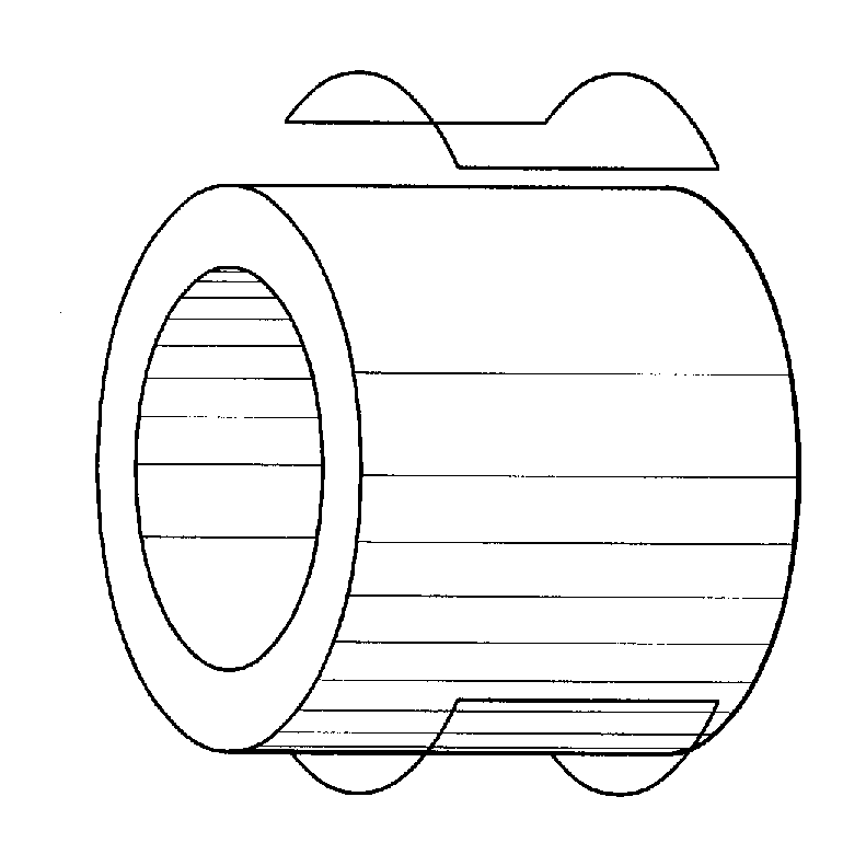
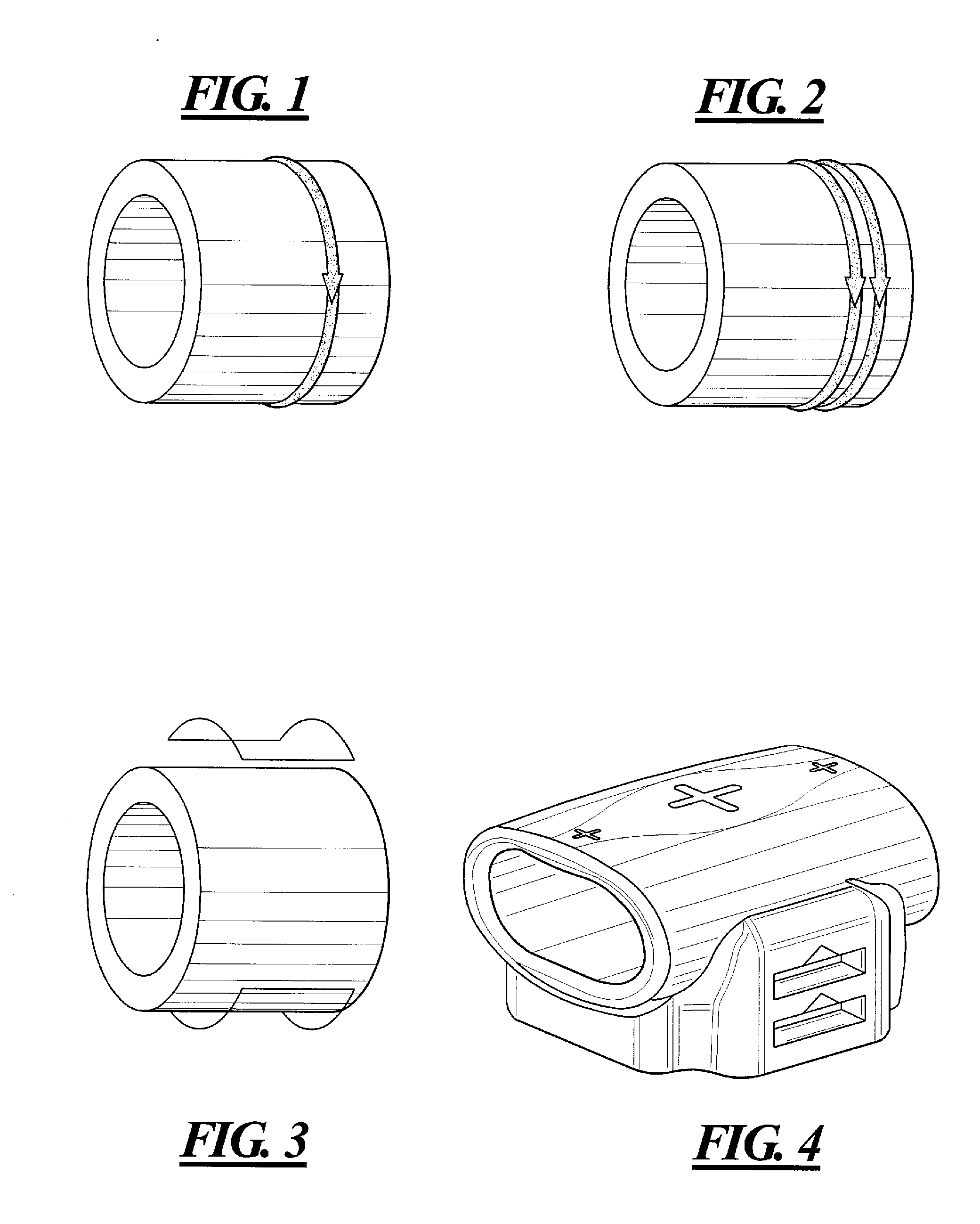
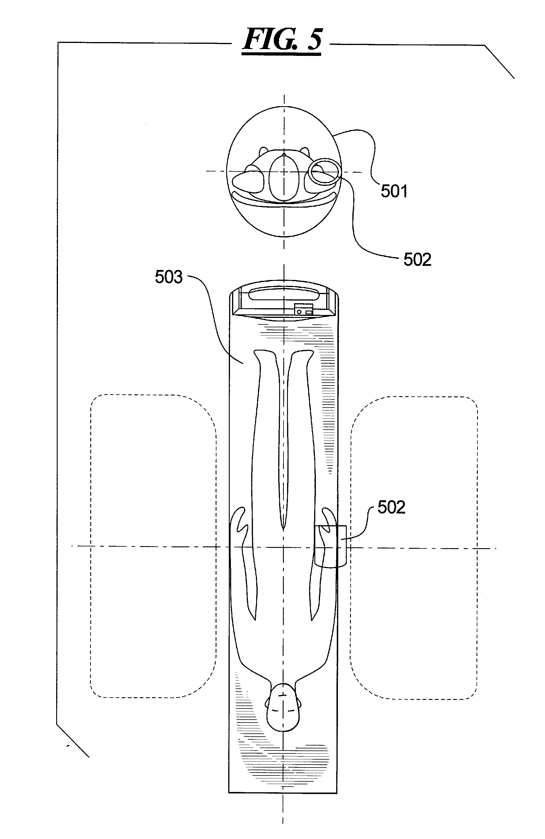
[0033]The basis of the present invention is to change the manner of positioning a patient's limb from being parallel to the direction of the basic magnetic field, as in the prior art; to positioning the patient's limb perpendicular to the direction of the basic magnetic field, so that a loop type coil can be used as the receiving coil, so as to achieve a relatively high SNR.

[0034]In the present invention the direction of a wrist coil is turned by 90°, so that the basic magnetic field generated by a basic magnet is perpendicular to the direction of the patient's limb, thus a loop type coil, such as a single loop coil, a solenoid coil, a Helmholtz pair, etc., can be used as the receiving coil.

[0035]In the present invention a material meeting certain requirements by an application environment is used to make a bracket for supporting and positioning of the receiving coil. One manner for realizing the bracket is to make it from a non-ferromagnetic and insulating material of good MRI comp...


PUM


Abstract

In a high field magnetic resonance imaging apparatus and a method for obtaining signals having a high signal-to-noise ratio with the receiving coil thereof, the apparatus has at least a basic magnet and a receiving coil, the basic magnet generating a basic magnetic field, and the receiving coil being disposed within the basic magnetic field and forming an accommodating cavity. The accommodating cavity of the receiving coil is perpendicular to the direction of the basic magnetic field and is positioned in the field of view of the apparatus. The receiving coil is a loop type coil. The apparatus can further have a bracket for fixing the receiving coil. In the method, a receiving coil is used to receive signals in a magnetic field, wherein the receiving coil is perpendicular to the direction of the magnetic field. By using the apparatus and the corresponding method since the receiving coil can have a loop type design, the signal-to-noise ratio is increased. Moreover, the receiving coil can be disposed at a position closer to the center of the field of view, so that the imaging quality is improved.

Description

BACKGROUND OF THE INVENTION[0001]1. Field of the Invention[0002]The present invention relates to a magnetic resonance imaging (MRI) apparatus, and particularly to a high field magnetic resonance imaging apparatus and a method for obtaining a high signal-to-noise ratio by a receiving coil thereof.[0003]2. Description of the Prior Art[0004]Magnetic resonance imaging is an imaging technology for obtaining the internal structural information of an object by means of the magnetic resonance phenomena. MRI is broadly used in the field of medical imaging due to its significant advantages, such as a large number of imaging parameters, high resolution, tomography in any layer required, non-destructive imaging, etc.[0005]In a middle or low field MRI apparatus (basic magnetic field=0.5T), the direction of the basic magnetic field is perpendicular to the patient's limb in a receiving coil. A radio frequency (RF) receiving coil is usually a loop (i.e. loop type) coil, such as a single loop coil s...

Claims


Application Information

Patent Timeline
Patent Type & Authority Applications(United States)
IPC IPC(8): G01R33/48G01R33/34
CPCG01R33/34053G01R33/341G01R33/34061
Inventor XUE, TING QIANGWANG, JIAN MINHE, ZENG HEWANG, YANG
Owner SIEMENS HEALTHCARE GMBH
Why Eureka
Try Eureka