Supercharge Your Innovation With Domain-Expert AI Agents!

Dsrc communication circuit and dsrc communication method

a communication circuit and communication circuit technology, applied in the field of ds, can solve problems such as shifting between original timing and accumulation of slot timing shifts, and achieve the effect of preventing uw detection errors

Inactive Publication Date: 2008-08-28
PANASONIC CORP
View PDF34 Cites 20 Cited by
  • Summary
  • Abstract
  • Description
  • Claims
  • Application Information

AI Technical Summary

Benefits of technology

[0012]It is therefore an object of the present invention to provide a DSRC communication circuit and DSRC communication method capable of preventing UW detection errors resulting from shifts in timing of received data and UW detection windows.
[0013]It is a further object of the present invention to provide a DSRC communication circuit and DSRC communication method capable of supporting data reception for one or a plurality of modulation schemes using a circuit configuration taking into consideration simplicity, reduced dimension and low power consumption.

Problems solved by technology

However, this kind of DSRC communication of the related art has the following problems to resolve.
However, in the received data, there are cases where shift occurs between the original timing and the actual demodulation timing as a result of the influence of fading, or the like according to the environment where communication is carried out.
This results in the occurrence of a situation where shifts in frame timing and slot timing accumulate as a result of carrying out UW detection of receiving slots where the timing is shifted using UW detection windows in which shifts in the frame timing and slot timing are reflected.
As a result, a UW detection error occurs that the timing of received data and the timing of the UW detection window do not match, and there is a problem that it becomes necessary to wait retransmission of the data or carry out processing for consecutive UW reception.

Method used


Image

  • Dsrc communication circuit and dsrc communication method
  • Dsrc communication circuit and dsrc communication method
  • Dsrc communication circuit and dsrc communication method

Examples


embodiment 1

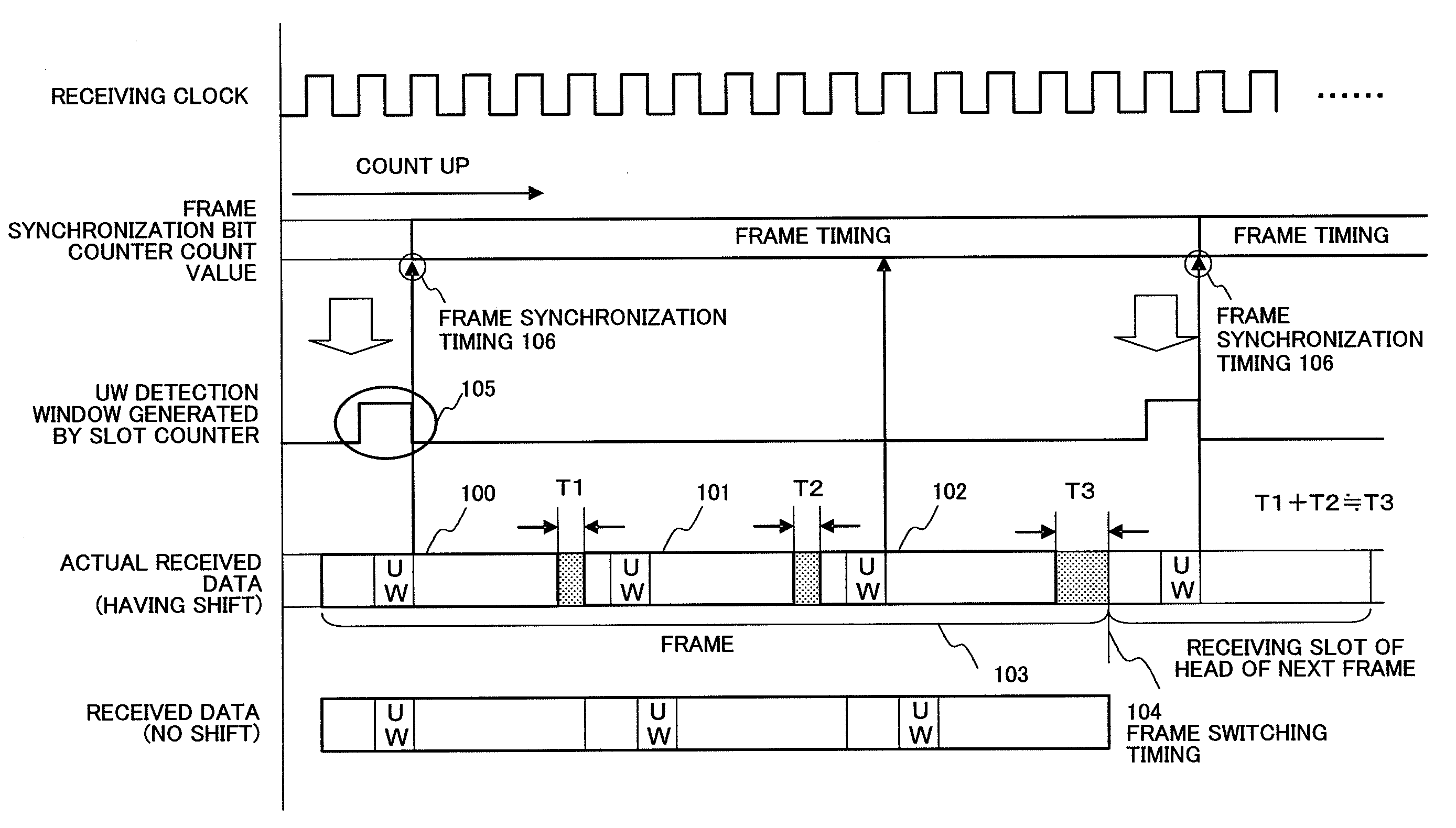
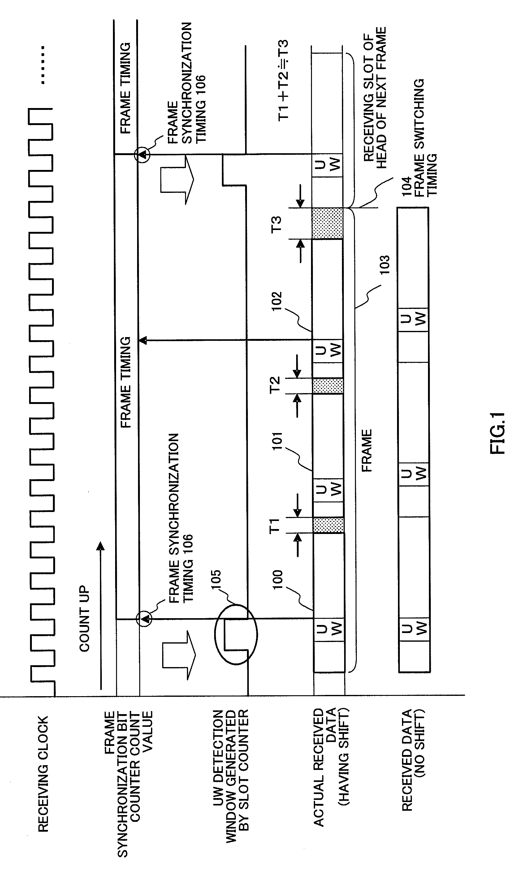
[0025]FIG. 1 is a timing diagram showing the relationship between received data and its shifts, frame synchronization timing of a frame synchronization bit counter, frame timing, and timing of a UW detection window for a DSRC communication circuit and DSRC communication method according to Embodiment 1 of the present invention.

[0026]Received data in DSRC communication is formed with a bit sequence of PR (preamble) and UW (unique word), a received data body, a bit sequence of CRC data and guard time. Communication frame 103 is formed with receiving slot 100 which is the head of a frame, and receiving slots 101 and 102 which is other than the head of the frame. Further, 104 is a frame switching timing which is the cut-off for a frame, and 105 is a UW detection window.

[0027]In the following, the operation of the DSRC communication circuit and DSRC communication method having the above-described configuration will be described.

[0028]In the DSRC communication standard, received data for ...

embodiment 2

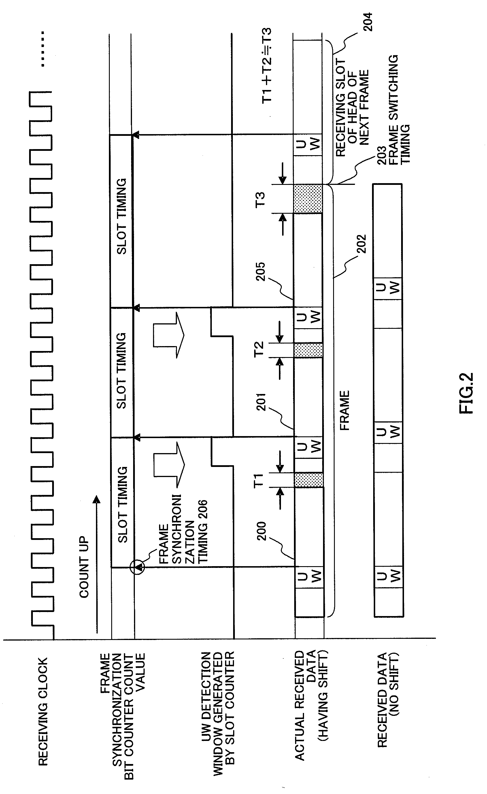
[0035]FIG. 2 is a timing diagram showing a relationship between received data and its shifts, slot synchronization timing of a slot synchronization bit counter, slot timing, and timing of a UW detection window for a DSRC communication circuit and DSRC communication method according to Embodiment 2 of the present invention.

[0036]It is necessary to perform reception processing such as simple privacy scrambling and data scrambling on the bit sequence after UW, CRC operation, and error correction operation on the received data, and store necessary data out of the received data in a receiving buffer. Therefore, at all receiving slots, it is necessary to detect UW from bit sequences for the received data, know the position and timing of the currently receiving data, and generate reception processing timing at the reception processing circuit and timing for storing the necessary data in the receiving buffer. However, the timing of slots within a frame is defined in the DSRC communication s...

embodiment 3

[0042]FIG. 3 is a block diagram showing a configuration of receiving circuit of a DSRC communication circuit and a communication method according to Embodiment 3 of the present invention, and shows the relationship between a UW detection section, clock transferring section, reception processing circuit and receiving reference clock generating section.

[0043]In FIG. 3, DSRC receiving circuit 300 is configured with antenna 301, RF circuit 302, modem 303, UW detecting section 310, clock transferring section 311, reception processing circuit 312, receiving reference clock generating section 313 that has dividing circuit 313a, receiving timing generating section 314 and receiving buffer 315.

[0044]UW detecting section 310 determines a unique word bit sequence through comparison with a bit sequence pattern of the unique word set in advance and generates a unique word detection signal.

[0045]Clock transferring section 311 temporally stores the received data in synchronization with a demodulat...


PUM


Abstract

A DSRC communication and DSRC communication method for preventing UW detection errors as a result of shifts in timings of received data and a UW detection window. A configuration is adopted where a frame timing generating section that receives a UW detection window timing signal of a receiving slot of the head of a frame, synchronizes frames, and counts up a first synchronization bit counter to generate a frame timing, and a UW detection window timing generating section that generates a timing signal for a UW detection window of a receiving slot of the head of the next frame using the generated frame timing as a reference, are provided, and the frame timing is maintained by taking the UW detection timing at receiving slot 100 of the head of the frame as frame synchronization timing 106, and loading and counting up a value of frame synchronization bit counter within the receiving circuit at frame synchronization timing 106.

Description

CROSS REFERENCE TO RELATED APPLICATIONS[0001]The disclosure of Japanese Patent Application No. 2005-254137 filed on Sep. 1, 2005 including the specification, drawings and abstract is incorporated herein by reference in its entirety.BACKGROUND OF THE INVENTION[0002]1. Field of the Invention[0003]The present invention relates to a DSRC (Dedicated Short Range Communication) communication circuit and DSRC communication method for use in a dedicated short range communication (DSRC) wireless system.[0004]2. Description of the Related Art[0005]The narrow band communication system is directed to a narrow range of road-to-vehicle communication such as an electronic toll collection system (ETC) and commercial vehicle management system, and is a communication scheme capable of high-speed data communication (4 Mbps). Up until now, schemes employing optical signals and schemes employing radio wave have been developed, and a communication-possible range is typically from a few meters to several h...

Claims


Application Information

Patent Timeline
IPC IPC(8): H04L7/00
CPCH04W56/00H04B7/2643
Inventor OYAMA, SHIGEKI
Owner PANASONIC CORP
Features
  • R&D
  • Intellectual Property
  • Life Sciences
  • Materials
  • Tech Scout
  • Unparalleled Data Quality
  • Higher Quality Content
  • 60% Fewer Hallucinations
Learn More